Heater assembly with cavity filled with a potting compound

a technology of potting compound and potting compound, which is applied in the direction of respirators, tobacco, other domestic articles, etc., can solve the problems of electrical components deteriorating or failing in the aerosol-generating devi

Active Publication Date: 2022-08-16
PHILIP MORRIS PROD SA
View PDF11 Cites 0 Cited by
  • Summary
  • Abstract
  • Description
  • Claims
  • Application Information

AI Technical Summary

Problems solved by technology

The liquid that collects within the aerosol-generating device during use may leak into the interior of the aerosol-gene

Method used


Image

  • Heater assembly with cavity filled with a potting compound
  • Heater assembly with cavity filled with a potting compound
  • Heater assembly with cavity filled with a potting compound

Examples


Embodiment Construction

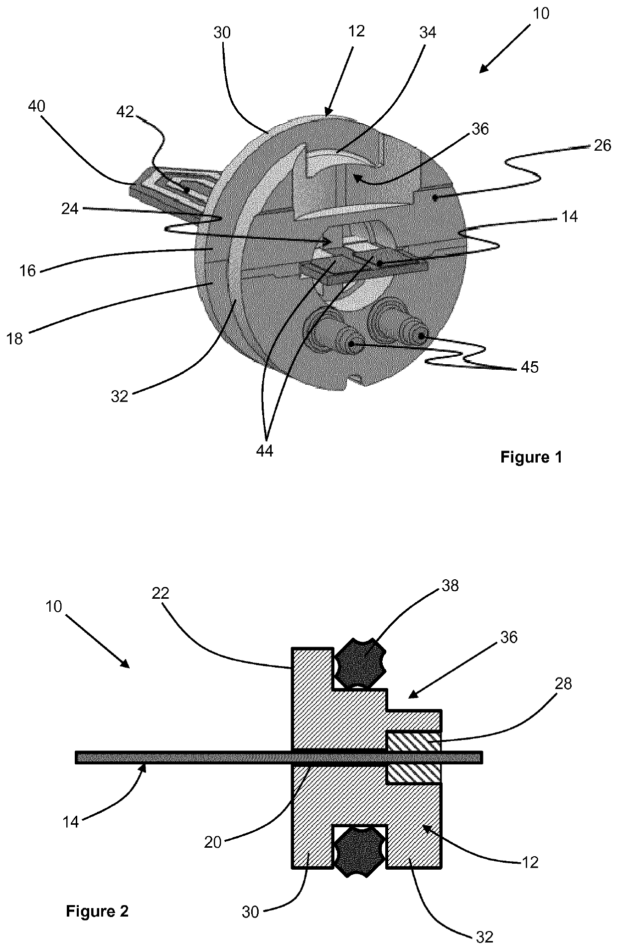
[0052]In some embodiments, the resistive heating element comprises one or more stamped portions of electrically resistive material, such as stainless steel. Alternatively, the resistive heating element may comprise a heating wire or filament, for example a Ni—Cr (Nickel-Chromium), platinum, tungsten or alloy wire.

[0053]In embodiments in which the heater assembly comprises at least one electrical contact, preferably the resistive heating element is electrically connected to the at least one electrical contact.

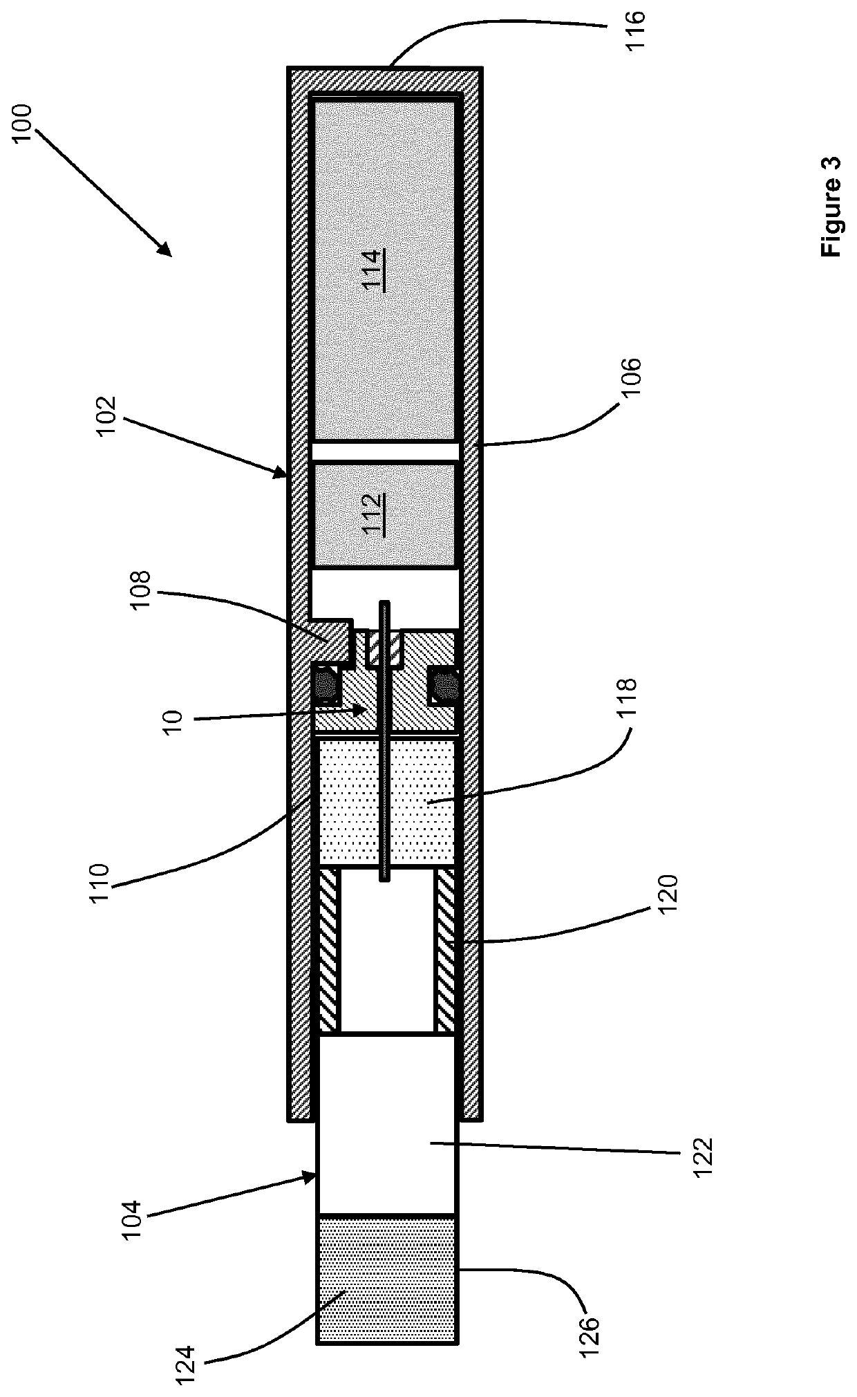
[0054]According to a second aspect of the present invention there is provided an aerosol-generating device comprising a heater assembly according to the first aspect of the present invention, in accordance with any of the embodiments described herein. The aerosol-generating device and the heater assembly may comprise any of the optional or preferred features described with respect to the first aspect of the present invention.

[0055]The aerosol-generating device comprises a housin...


PUM

PropertyMeasurementUnit
Poweraaaaaaaaaa

Abstract

A heater assembly for an aerosol-generating device is provided, the heater assembly including a bushing defining an aperture at a first end of the bushing and a cavity at a second end of the bushing; a potting compound disposed within the cavity; and an elongate electrical heater extending from the first end of the bushing, where a portion of the elongate electrical heater extends through the aperture and into the cavity. An aerosol-generating device, an aerosol-generating system, and a method of assembling a heater assembly for an aerosol-generating device are also provided.

Description

CROSS-REFERENCE TO RELATED APPLICATIONS[0001]This application is a U.S. national stage application of PCT / EP2018 / 070519, filed on Jul. 27, 2018, which is based upon and claims the benefit of priority from European patent application no. 17183836.0, filed Jul. 28, 2017, the entire contents of each of which are incorporated herein by reference.TECHNICAL FIELD[0002]The present invention relates to a heater assembly for an aerosol-generating device, the heater assembly having a cavity. The present invention also relates to an aerosol-generating device comprising the heater assembly, an aerosol-generating system comprising the aerosol-generating device, a method of generating an aerosol, and a method of assembling a heater assembly.DESCRIPTION OF THE RELATED ART[0003]One type of aerosol-generating system is an electrically operated smoking system. Known handheld electrically operated smoking systems typically comprise an aerosol-generating device comprising a battery, control electronics...

Claims


Application Information

Patent Timeline
IPC IPC(8): A24F40/46A61M15/06A24F40/70B29C45/14H05B3/03H05B3/44A24F40/20B29L31/18B29L31/00A24F40/10
CPCA61M15/06A24F40/46A24F40/70B29C45/14336H05B3/03H05B3/44A24F40/20B29C2045/14459B29L2031/18B29L2031/7414A61M2016/0024A61M2016/0039A61M2205/3317A61M2205/3653A61M11/042A24F40/10A61M2205/8206A24F40/50
Inventor AW, SZE CHIEKFRINGELI, JEAN LUCYEO, CHOW KIAN
Owner PHILIP MORRIS PROD SA
Why Eureka
Try Eureka