Cooling plate for the temperature control of at least one battery cell and a battery system

a technology of cooling plate and battery cell, which is applied in the direction of cell components, cell component details, electrochemical generators, etc., can solve the problem of not always being able to reliably control the temperature of the traction battery cell

Active Publication Date: 2022-08-16
ROBERT BOSCH GMBH
View PDF5 Cites 2 Cited by
  • Summary
  • Abstract
  • Description
  • Claims
  • Application Information

AI Technical Summary

Benefits of technology

[0004]This has the advantage of providing an improved cooling performance or temperature control as compared to the prior art, so that a reliable temperature control of the at least one battery cell is possible. The increased turbulence which can be produced by means of the opening of the at least one perturbing contour and / or the further opening of the at least one perturbing contour serves for a more intense mixing of the coolant. In particular, a laminar flow formed by the coolant within the flow space, especially a laminar flow formed along a longitudinal direction of the cooling plate, is perturbed such that a temperature gradient perpendicular and / or parallel to the longitudinal direction is minimized. The opening and / or the further opening produces and / or produce for example a turbulent flow with eddy currents in the coolant. Preferably, the opening and / or the further opening produces and / or produce for example a flow with a Reynolds number over 100, preferably over 1000, especially preferably over 2000.
[0036]A battery system comprising a cooling plate according to the present invention and a battery module, wherein the battery module comprises at least one battery cell and the at least one battery cell is arranged on the first cover so that a thermal contacting of the at least one battery cell and the first cover is formed, is especially user-friendly. In particular, a changing of the battery module and / or the at least one battery cell is especially easy, since for example the cooling circuit does not need to be opened during the change.

Problems solved by technology

Such cooling plates have the drawback that a reliable temperature control of the traction battery cells is not always possible.

Method used


Image

  • Cooling plate for the temperature control of at least one battery cell and a battery system
  • Cooling plate for the temperature control of at least one battery cell and a battery system
  • Cooling plate for the temperature control of at least one battery cell and a battery system

Examples


Embodiment Construction

[0042]In the various variant embodiments, the same parts are given the same reference numbers.

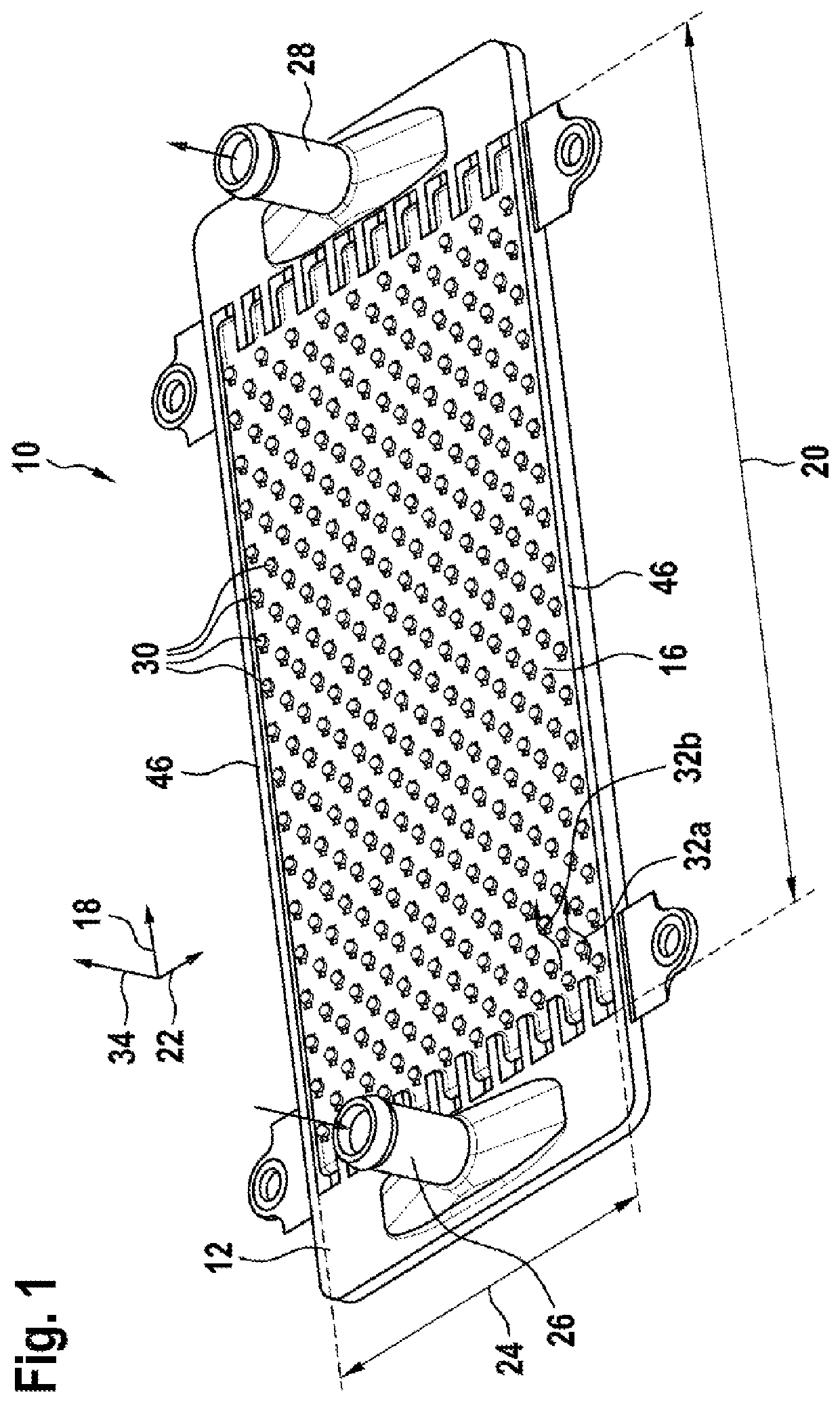
[0043]FIG. 1 shows in a perspective view one embodiment of a cooling plate 10 according to the invention for the temperature control of at least one battery cell.

[0044]The cooling plate 10 comprises a frame 12. The frame in the exemplary embodiment shown in FIG. 1 is made of plastic. The frame 12 comprises a flow space 16. The flow space 16 has a flow space length 20 in a longitudinal direction 18 of 40 cm for example. In alternative embodiments, the value of the flow space length 20 depends on the technical requirements, especially a dimensioning of the battery cell, such as the physical dimensions. The flow space length 20 in particular may be between 10 cm and 80 cm, preferably between 20 cm and 60 cm, especially preferably between 30 cm and 50 cm.

[0045]The flow space 16 in the exemplary embodiment shown in FIG. 1 has a flow space width 24 in a width direction 22 of 10 cm for example. In...


PUM

PropertyMeasurementUnit
Reynolds numberaaaaaaaaaa

Abstract

A cooling plate (10) for temperature control of a battery cell, having a frame (12) with a coolant flow space (16) and at least one perturbing contour (30) inside the flow space (16), which is provided to increase turbulence in the coolant and is designed to support the at least one battery cell or for mechanical contacting with a cover (14) of the flow space (16). The perturbing contour (30) is arranged such that the coolant can flow around the perturbing contour (30) and the perturbing contour (30) is formed in the manner of at least one opening (50) in such a way that the coolant can flow through the at least one perturbing contour (30) and / or the frame (12) forms an opening (52) beneath the perturbing contour (30) in such a way that the coolant can flow beneath the at least one perturbing contour (30).

Description

BACKGROUND OF THE INVENTION[0001]The invention relates to a cooling plate for the temperature control of at least one battery cell. Furthermore, the invention also relates to a battery system with such a cooling plate.[0002]Cooling elements are known from US2014 / 138063 for the temperature control of electronic devices, having perturbing contours in a flow space for a coolant. Such cooling plates have the drawback that a reliable temperature control of the traction battery cells is not always possible.SUMMARY OF THE INVENTION[0003]The present invention describes a cooling plate for the temperature control of at least one battery cell, especially for a traction battery. The cooling plate comprises a frame with a flow space designed for the throughflow of a coolant and at least one perturbing contour arranged inside the flow space. The perturbing contour is provided to increase the turbulence in the coolant flowing through the flow space and is designed to support the at least one batt...

Claims


Application Information

Patent Timeline
Patent Type & Authority Patents(United States)
IPC IPC(8): H01M10/6554H01M10/6556H05K7/20H01M50/20
CPCH01M10/6554H01M10/6556H05K7/20254H01M10/613H01M10/6551H01M10/6568H01M50/20H01M10/6567H01M10/6566Y02E60/10
Inventor SCHMITT, MARKUSRUEHLE, ANDREASKOPP, BENJAMIN
Owner ROBERT BOSCH GMBH
Why Eureka
Try Eureka