Induction cooker capable of installing sleeve

A technology for installing a sleeve and an induction cooker, applied in the field of induction cookers, can solve the problems of unreliable panel heat transfer and inaccurate temperature control of the induction cooker, etc., and achieve the effects of reliable temperature control and accurate temperature sensing.

Inactive Publication Date: 2007-02-21
甘柏海
View PDF0 Cites 0 Cited by
  • Summary
  • Abstract
  • Description
  • Claims
  • Application Information

AI Technical Summary

Problems solved by technology

[0003] From the perspective of existing induction cooker technology, its temperature measuring device is installed under the panel of the induction cooker, and the temperature measuring device and the heated parts are separated by the panel. Due to changes in the environment and temperature, the heat transfer of the panel is not reliable, making the temperature control of the induction cooker inaccurate.

Method used


Image

  • Induction cooker capable of installing sleeve
  • Induction cooker capable of installing sleeve
  • Induction cooker capable of installing sleeve

Examples


specific Embodiment approach 2

[0044] (magnetic switch)

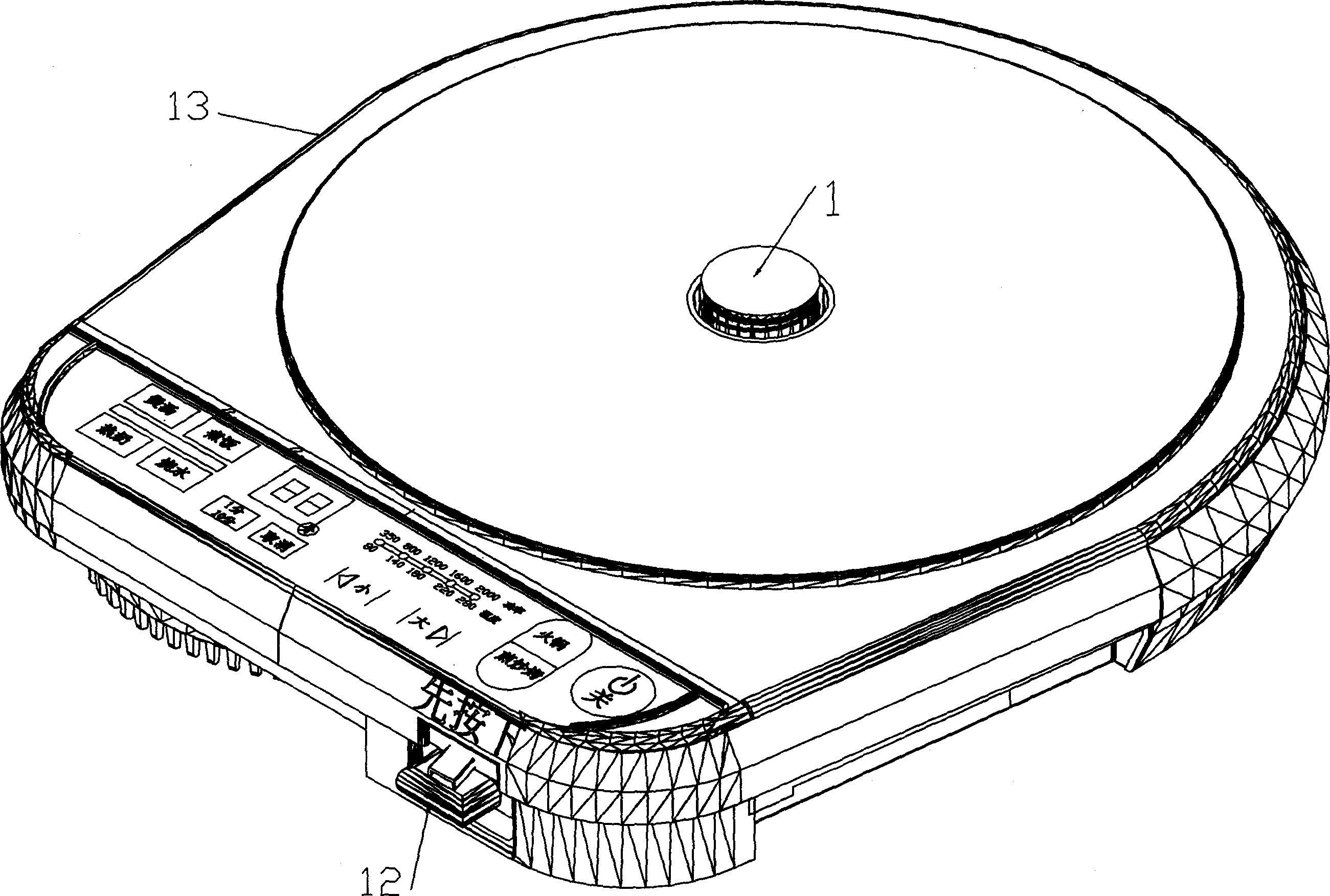
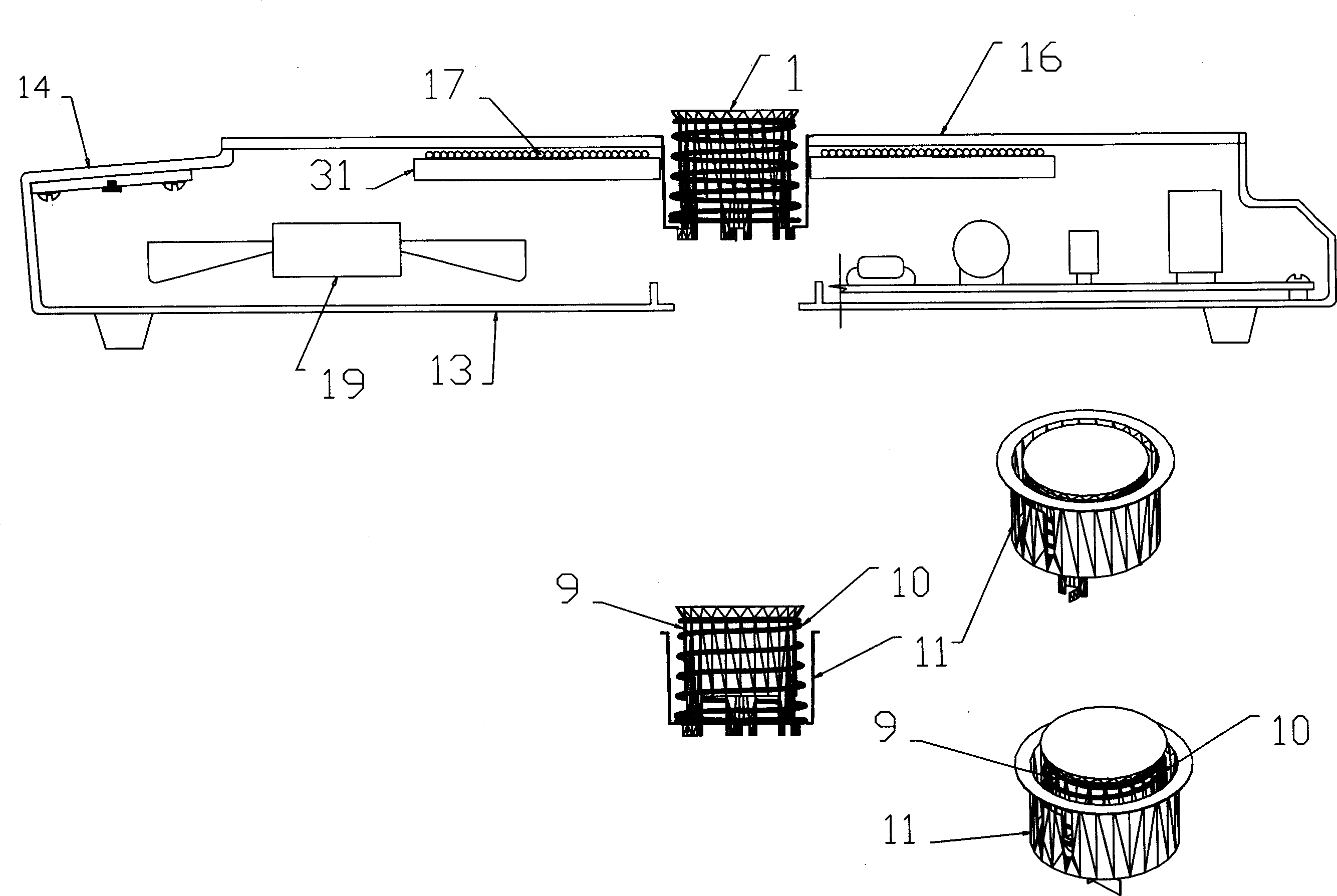
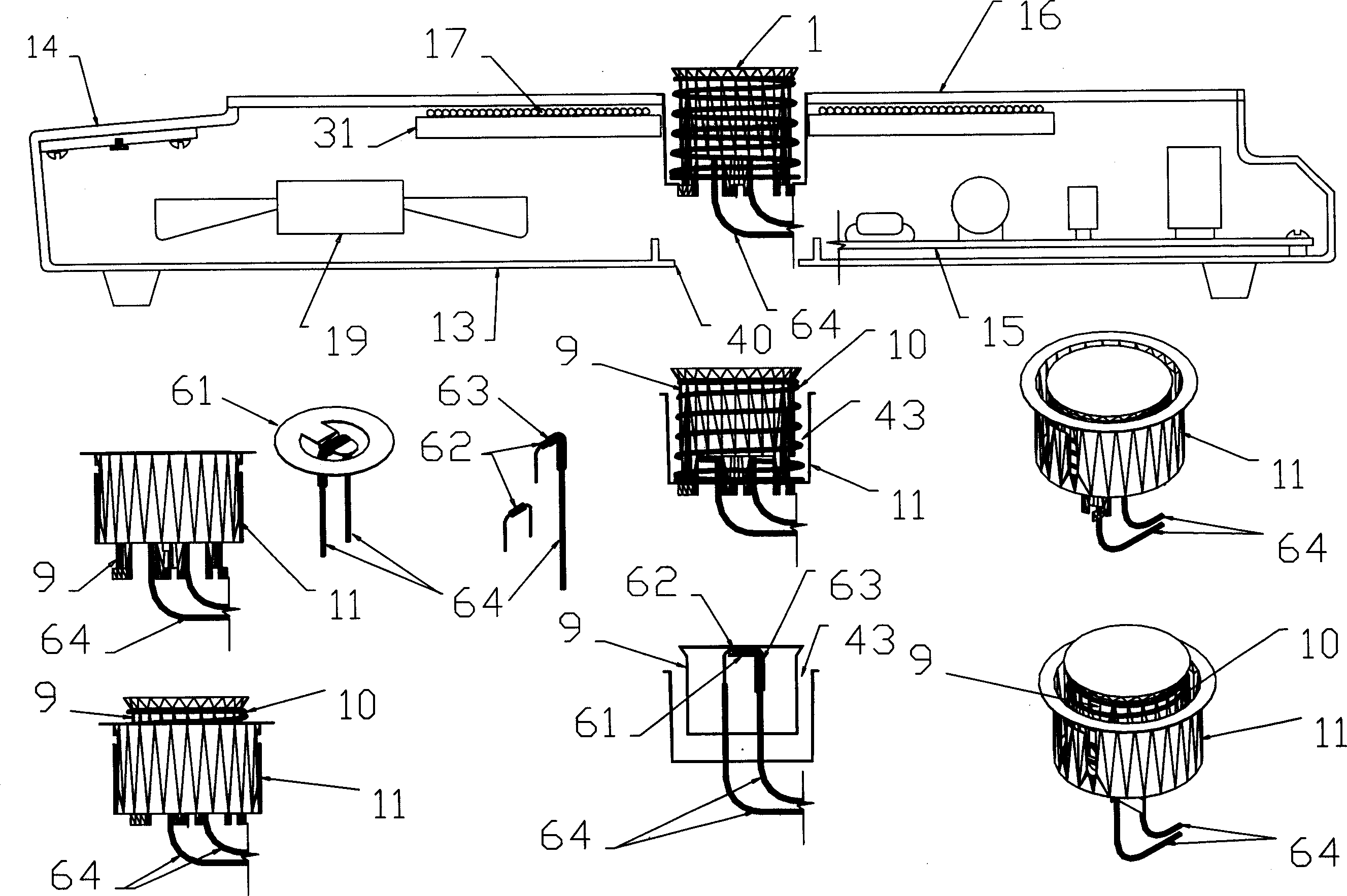
[0045] The pot 26 is placed on the panel 16 on the induction cooker 13, the magnetic control device 1 is pressed down, and then the operating handle 12 is pressed by hand, the lever 18 rotates counterclockwise through the rotating shaft 36 on the support 38, and the left end of the lever 18 is Next, the normally closed contact 21 is disconnected, and the contact 21 disconnects the shutdown circuit or the heat preservation circuit of the control panel 14 and the control circuit 15.

[0046] The right end of lever 18 pushes connecting rod 8 upwards and jacks up lower holder 7 together with lower magnet 6, and upper magnet 3 and lower magnet 6 attract each other, and small spring 5 is compressed. The lever 18 is kept stable so that the normally closed contact 21 is disconnected, and the normally closed contact 21 keeps disconnecting the shutdown circuit or the heat preservation circuit of the control circuit 15 .

[0047] After t...


PUM


Abstract

An electromagnetic stove enabling to erect sleeve on it is featured as opening hole on magnetic force coil and face plate of said stove for erecting sleeve, contacting sleeve with heating component on face plate and setting temperature control element in sleeve, detecting temperature of heating component by temperature control element through sleeve.

Description

[0001] The invention relates to an electromagnetic cooker, especially an electromagnetic cooker with a sleeve installed on the magnetic coil and the panel. The sleeve can extend out of the panel to contact the heated parts. A magnet, a thermistor or a thermoelectric corner, a magnet or a thermistor are installed in the sleeve. Or the thermoelectric corner receives the temperature of the heating components on the panel of the induction cooker through the top cover of the sleeve, so that the temperature control of the induction cooker is more accurate, and the magnet or thermistor or the thermoelectric corner is also protected by the sleeve. technical field [0002] The invention belongs to the field of electromagnetic cooker Background technique [0003] From the perspective of existing induction cooker technology, its temperature measuring device is installed under the panel of the induction cooker, and the temperature measu...

Claims


Application Information

Patent Timeline
Patent Type & Authority Applications(China)
IPC IPC(8): F24C7/00F24C7/08
Inventor 甘柏海
Owner 甘柏海
Why Eureka
Try Eureka