Orthodontic braces and feet orthotics with backscatter based sensors

a technology of backscatter and orthotics, applied in the field of orthotics with backscatter based sensors, can solve the problems of specialized equipment, large footprint, and high cost of prior art imaging techniques, and achieve the effects of reducing the risk of recurrence, and reducing the diagnostic accuracy

Active Publication Date: 2022-08-23
AKSELROD DAVID
View PDF60 Cites 0 Cited by
  • Summary
  • Abstract
  • Description
  • Claims
  • Application Information

AI Technical Summary

Benefits of technology

[0031]Present inventions discussed herein may include substantially optically clear orthodontic braces and feet orthotics (collectively referred to as “appliances”) with backscatter based sensors. These two categories of otherwise different appliances share a common property requiring that the given appliance must be correctly custom manufactured to fit the patient's own particular geometry and dimensions of their teeth and / or feet in order to perform as intended. Incorporating such appliances with backscatter based sensors enables simple, easy, fast, efficient, and cost effective measurements, in real-time or near real-time, of stresses, forces, structural changes, and / or the like in the given appliance; which in turn can aid in determining if adjustments or re-manufacture of appliance may be needed or desired; and / or wherein such measurements may aid in evaluating performance of the given appliance. In some embodiments, such measurements may also be taken remotely away from the practitioner (e.g., away from the orthodontist or away from the pediatrist); and the remotely generated measurement data may be communicated to the practitioner via standard network communication technology.
[0032]It is an objective of the present invention to provide an imaging system and an imaging method that may be comparatively less expensive to use and implement as compared against traditional X-ray, CT-scan, MRI, ultrasound, radar, or the like imaging systems.
[0033]It is another objective of the present invention to provide an imaging system and an imaging method that may be comparatively easy and simple to use and implement as compared against traditional X-ray, CT-scan, MRI, ultrasound, radar, or the like imaging systems.

Problems solved by technology

Prior art imaging techniques, such as, X-ray, CT-scan, MRI, ultrasound, radar, and / or the like generally involve expensive (expensive to buy, lease, use, train, maintain, etc.), specialized, complicated equipment, and / or equipment that may occupy a relatively large footprint.
And in many applications the electromagnetic energy emitted for imaging purposes from some prior art imaging systems may be dangerous or destructive to the object being imaged and thus such imaging must be minimized to prevent problems from overexposure.
A prime example of this is the use of X-rays to image hard (dense) structures in biologic samples, such as teeth and bones in vertebrates; where overexposure to X-rays may lead to undesirable mutations and cancers.
And even in the case of inanimate objects, such objects may also still be prone to deterioration (e.g., becoming brittle) resulting from overexposure to emitted high energy imaging electromagnetic radiation, such as X-rays.
In many instances, if overexposure was not a problem, practitioners would then prefer to utilize such imaging techniques more frequently thus significantly increasing probability of discovering issues earlier in time.
In some instances, such as with cancer patients or with pregnant women, use of X-rays is necessarily restricted.
Changes in a patient's gate, physical changes in his / her feet, physical changes in the said orthotic insoles or other changes may diminish the effectiveness of the treatment.
However, even if a patient were to request an additional re-evaluation, it would be done based on external scans of his / her feet and not based on the forces acting on his / her orthotic insoles during an active usage of the said insoles.
In this respect, mistakes in manufacturing of the said orthotic insoles may not be discovered and corrected.
For example, an orthodontic-archwire or an orthodontic expander may not be exerting correct force on some teeth due to variety of reasons such as miscalculation, different from expected changes in teeth development, materials fatigue, and / or other reasons.

Method used


Image

  • Orthodontic braces and feet orthotics with backscatter based sensors
  • Orthodontic braces and feet orthotics with backscatter based sensors
  • Orthodontic braces and feet orthotics with backscatter based sensors

Examples


Embodiment Construction

[0309]In the following discussion that addresses a number of embodiments and applications of the present invention, reference is made to the accompanying drawings that form a part thereof, where depictions are made, by way of illustration, of specific embodiments in which the invention may be practiced. It is to be understood that other embodiments may be utilized and changes may be made without departing from the scope of the invention.

[0310]Note, “fixed” as used herein may be with respect positional locations that are non-variable and / or non-self-moving; i.e., “fixed” as used herein may not refer to something being affixed or attached to something.

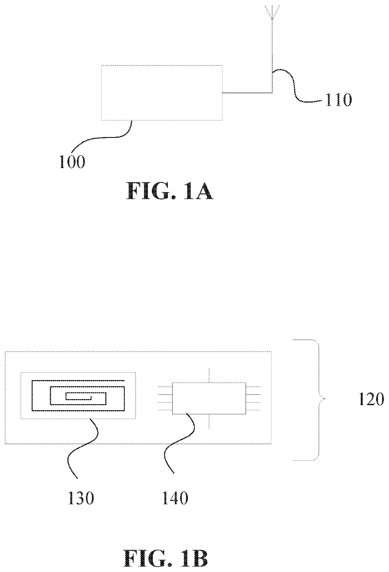
[0311]FIG. 1A may depict a schematic block diagram of a reader 100. In some embodiments, reader 100 may comprise antenna 110. In some embodiments, reader 100 may comprise at least one antenna 110. In some embodiments, reader 100 may comprise one or more antennas 110.

[0312]FIG. 1B may depict a schematic block diagram of a monitoring-senso...


PUM


Abstract

Inventions herein include at least mostly optically clear orthodontic braces and feet orthotics (collectively referred to as “appliances”) with backscatter based sensors. These two categories of appliances share a common property requiring that the given appliance must be correctly custom manufactured to fit a patient's own particular geometry and dimensions of their teeth and / or feet in order to perform as intended. Incorporating such appliances with backscatter based sensors enables simple, easy, fast, efficient, and cost effective measurements, in real-time or near real-time, of stresses, forces, structural changes, and / or the like in the given appliance; which in turn can aid in determining if adjustments or re-manufacture of the appliance may be needed or desired; and / or wherein such measurements may aid in evaluating performance of the given appliance. In some embodiments, such measurements may also be taken remotely away from a practitioner; and then communicated to a remotely located practitioner.

Description

PRIORITY NOTICE[0001]The present application claims priority under 35 U.S.C. § 119(e) to U.S. Provisional Patent Application Ser. No. 62 / 779,748 filed on Dec. 14, 2018, the disclosure of which is incorporated herein by reference in its entirety.[0002]The present patent application is a continuation-in-part (CIP) of U.S. non-provisional patent application Ser. No. 15 / 607,673 filed on May 29, 2017, and claims priority to said U.S. non-provisional patent application under 35 U.S.C. § 120. The above-identified patent application is incorporated herein by reference in its entirety as if fully set forth below.[0003]The present patent application is a continuation-in-part (CIP) of U.S. non-provisional patent application Ser. No. 15 / 653,461 filed on Jul. 18, 2017, and claims priority to said U.S. non-provisional patent application under 35 U.S.C. § 120. The above-identified patent application is incorporated herein by reference in its entirety as if fully set forth below.[0004]The present p...

Claims


Application Information

Patent Timeline
Patent Type & Authority Patents(United States)
IPC IPC(8): A61C7/08A61B5/0534A61B5/00H02J50/20
CPCA61C7/08A61B5/0031A61B5/0534A61B5/6847A61B2562/046A61B2562/08H02J50/20
Inventor AKSELROD, DAVID
Owner AKSELROD DAVID
Why Eureka
Try Eureka