Supercharge Your Innovation With Domain-Expert AI Agents!

Flush wallplate electrical box assembly

a wall plate and electrical box technology, applied in the field of electric boxes, can solve problems such as non-compliance with electrical codes

Active Publication Date: 2022-08-23
MON GEORGE EMMANUEL
View PDF11 Cites 2 Cited by
  • Summary
  • Abstract
  • Description
  • Claims
  • Application Information

AI Technical Summary

Benefits of technology

The patent text describes an electrical box that can be placed flush with a wall assembly and an optional wiring protection plate to protect wiring during installation. The electrical box can also be paired with a finish material interface flange that helps with air sealing and can also guide the placement of outlets. The finish material interface flange can be used with foam sealing tape or gaskets to provide exceptional air sealing without the use of messy putties or spray foam. Overall, the invention simplifies the placement and installation of electrical boxes and wiring protection during wall assembly construction.

Problems solved by technology

These installations, however, may require that the electrical box be placed at a non-standard depth relative to framing which can result in non-compliance with electrical codes.

Method used


Image

  • Flush wallplate electrical box assembly
  • Flush wallplate electrical box assembly
  • Flush wallplate electrical box assembly

Examples


Embodiment Construction

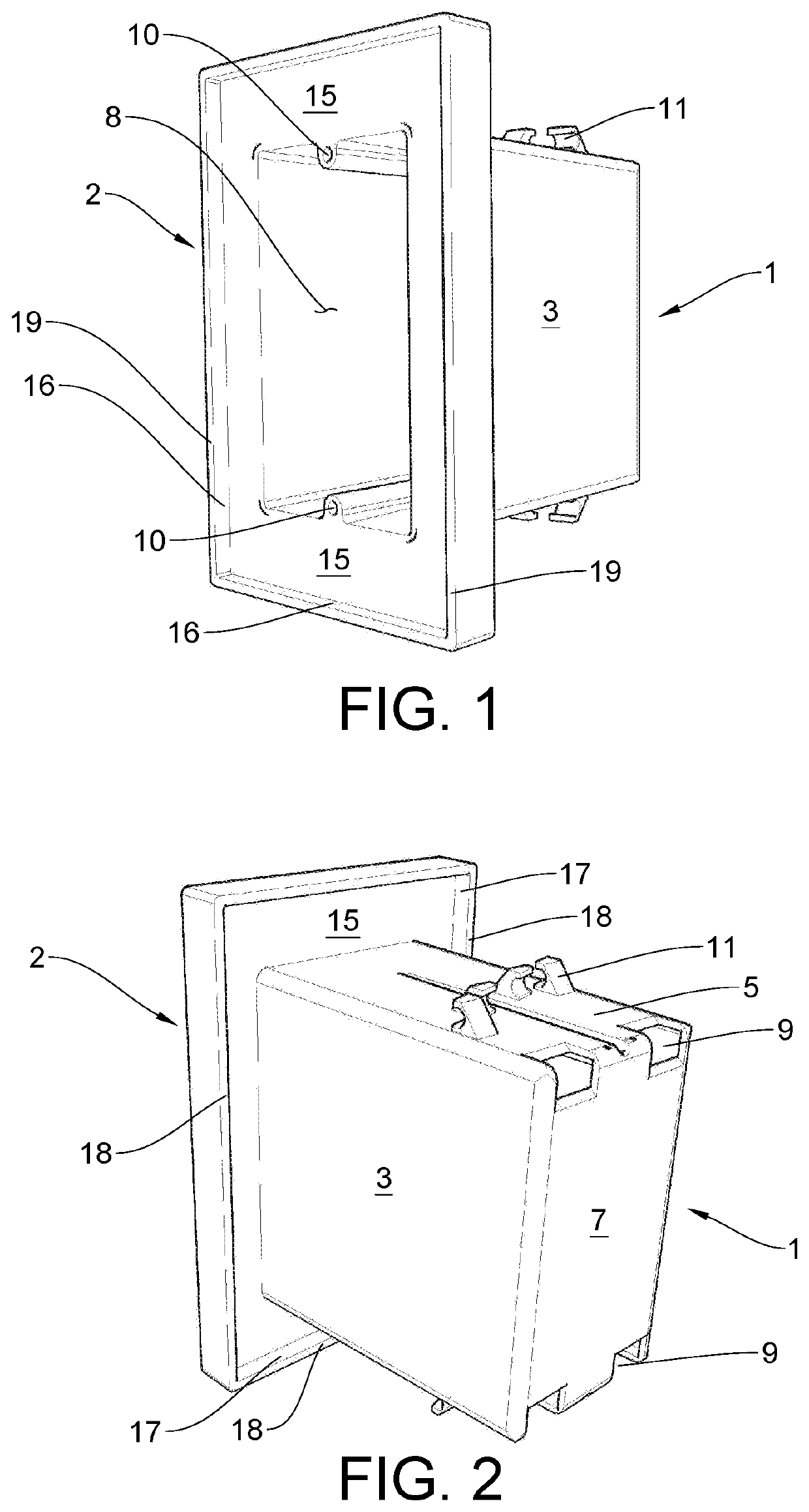
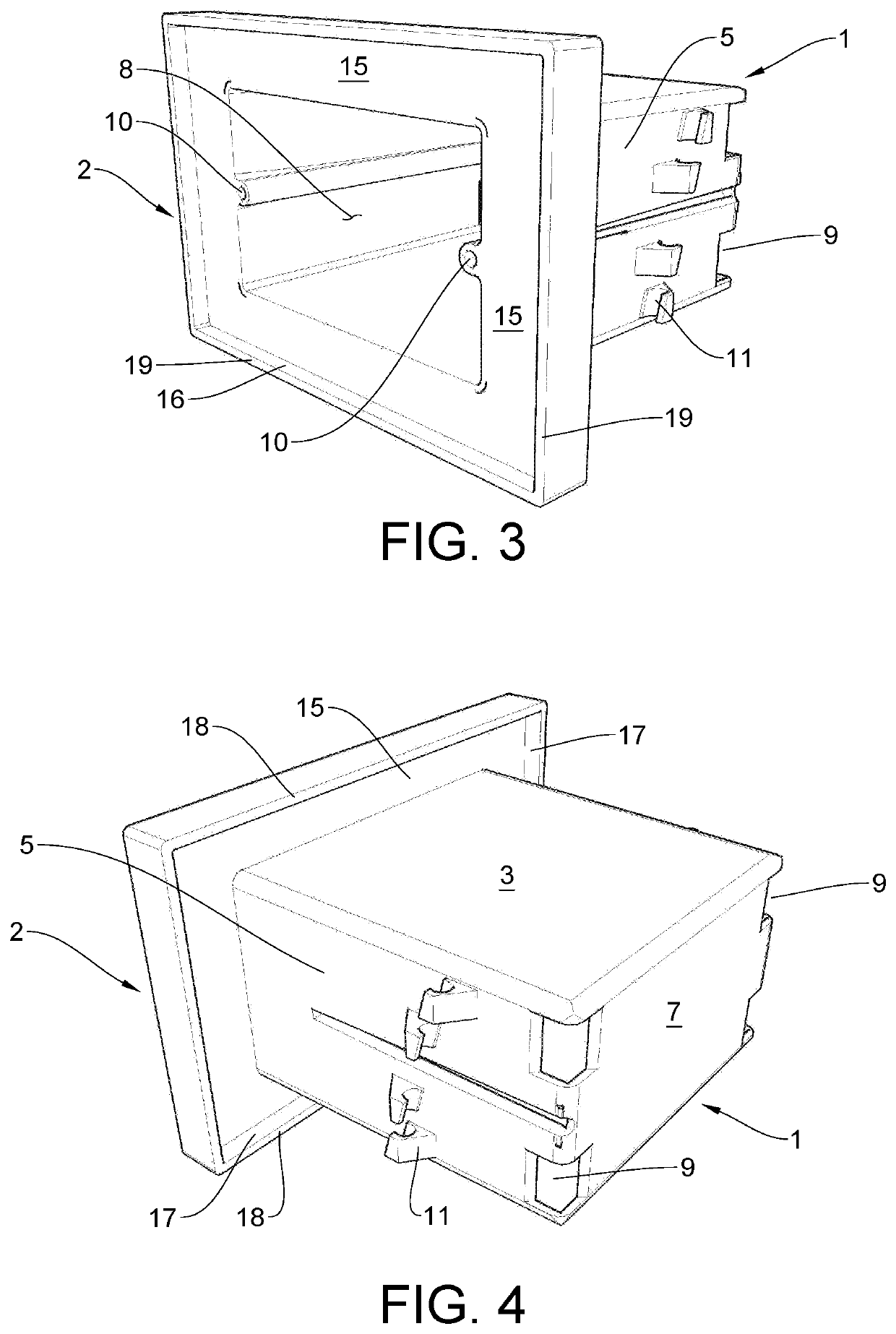
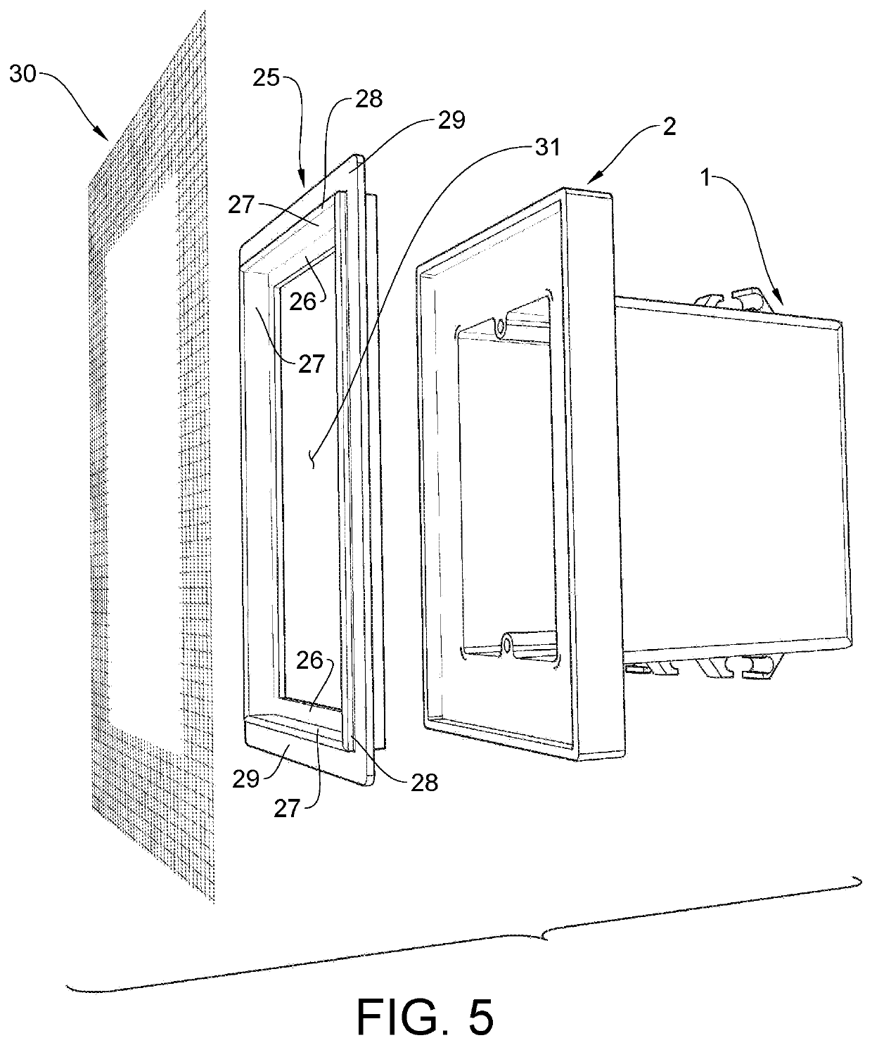
[0053]Referring to FIGS. 1-4: The flush wallplate electrical box preferred embodiment is an electrical box body (1) and flush wallplate housing (2) presented as a unitary structure. The electrical box body has four sides portions (3, 4, 5, 6) and a rectangular back portion (7) all formed together where they meet and with the front face (8) open (rectangular boxes) or a cylindrical shape and substantially round back portion formed together where they meet with the front face open (round boxes). The box body can be fastened to framing with standard fasteners placed through optional fastener clips (11) or openings described later in this detailed description. Within the box body are features such as knockouts or other types of openings (9) which enable cabling to enter and in some instances be secured, and threaded recesses (10) for receptacle and switch yokes to be mounted to the box using screws. Knock out tabs or other types of openings are, in some instances, sealed after electrica...


PUM


Abstract

The Flush Wallplate Electrical Box Assembly deploys and constrains an electrical wallplate such that the wallplate finished face is essentially co-planar to the surrounding wall assembly finish material finished surface. The assembly is comprised of flush wallplate electrical box possessing an integral housing intended to receive the electrical wallplate, an interface flange serving to interface between the electrical box and wall assembly finish materials, an interface placement guide to control the positioning of the interface flange and an element to protect wiring inside the electrical box during wall assembly construction. The form of the electrical box provides for a building and electrical code compliant installation and simplifies box positioning providing minimum variability. The interface flange provides for a consistent termination of wall assembly materials at the periphery of the electrical box.

Description

CROSS REFERENCE TO RELATED PATENT APPLICATIONS[0001]This application claims the benefit of U.S. Non-Provisional Utility patent application Ser. No. 17 / 493,558 filed Oct. 4 2021 by George E. Mon as sole inventor, the contents of which are incorporated herein by reference in its entirety.FIELD OF THE INVENTION[0002]The present invention relates to electrical boxes used in new and old work type electrical installations and specifically regards the manner in which these boxes interface with elements of the installation including outlets, wallplates, and wall assembly construction materials.BACKGROUND OF THE INVENTION[0003]Electrical enclosures, otherwise known as electrical boxes, are required by National Electrical Code for handling cable and connecting receptacles and switches to conductors in wall assemblies. They are generally of different types designed to be used in new or existing construction and to accommodate various quantities of cabling and outlets.[0004]Devices such as rece...

Claims


Application Information

Patent Timeline
IPC IPC(8): H02G3/12H02G3/14
CPCH02G3/12H02G3/14H02G3/123H02G3/126H02G3/081
Inventor MON, GEORGE EMMANUEL
Owner MON GEORGE EMMANUEL
Features
  • R&D
  • Intellectual Property
  • Life Sciences
  • Materials
  • Tech Scout
  • Unparalleled Data Quality
  • Higher Quality Content
  • 60% Fewer Hallucinations
Learn More