Thermal spray assembly and method for using it

Active Publication Date: 2017-01-26
ELEMENT SIX GMBH
View PDF2 Cites 4 Cited by
  • Summary
  • Abstract
  • Description
  • Claims
  • Application Information

AI Technical Summary

Benefits of technology

[0037]In some examples, the precursor material be suitable for depositing a hard layer of body. The deposited materi

Problems solved by technology

If the melting point of the precursor material is too low, there is a risk that material may evaporate while within the plasma jet and be lost

Method used


Image

  • Thermal spray assembly and method for using it
  • Thermal spray assembly and method for using it
  • Thermal spray assembly and method for using it

Examples


Embodiment Construction

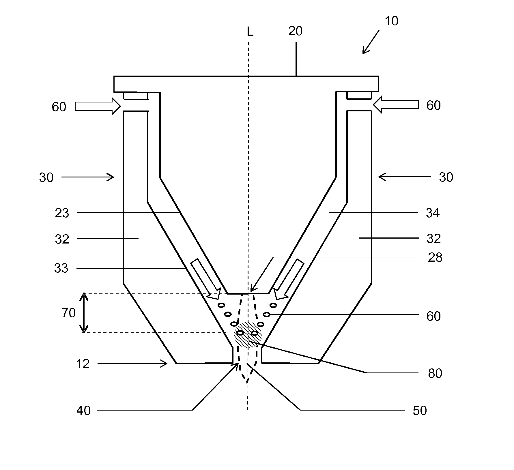
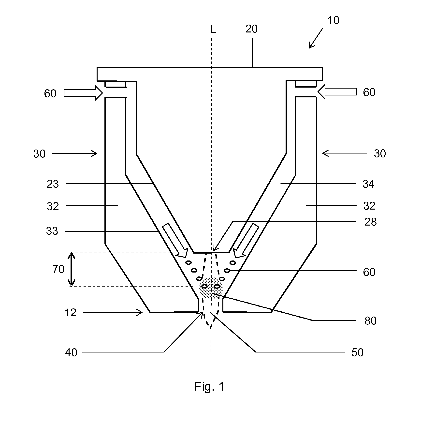
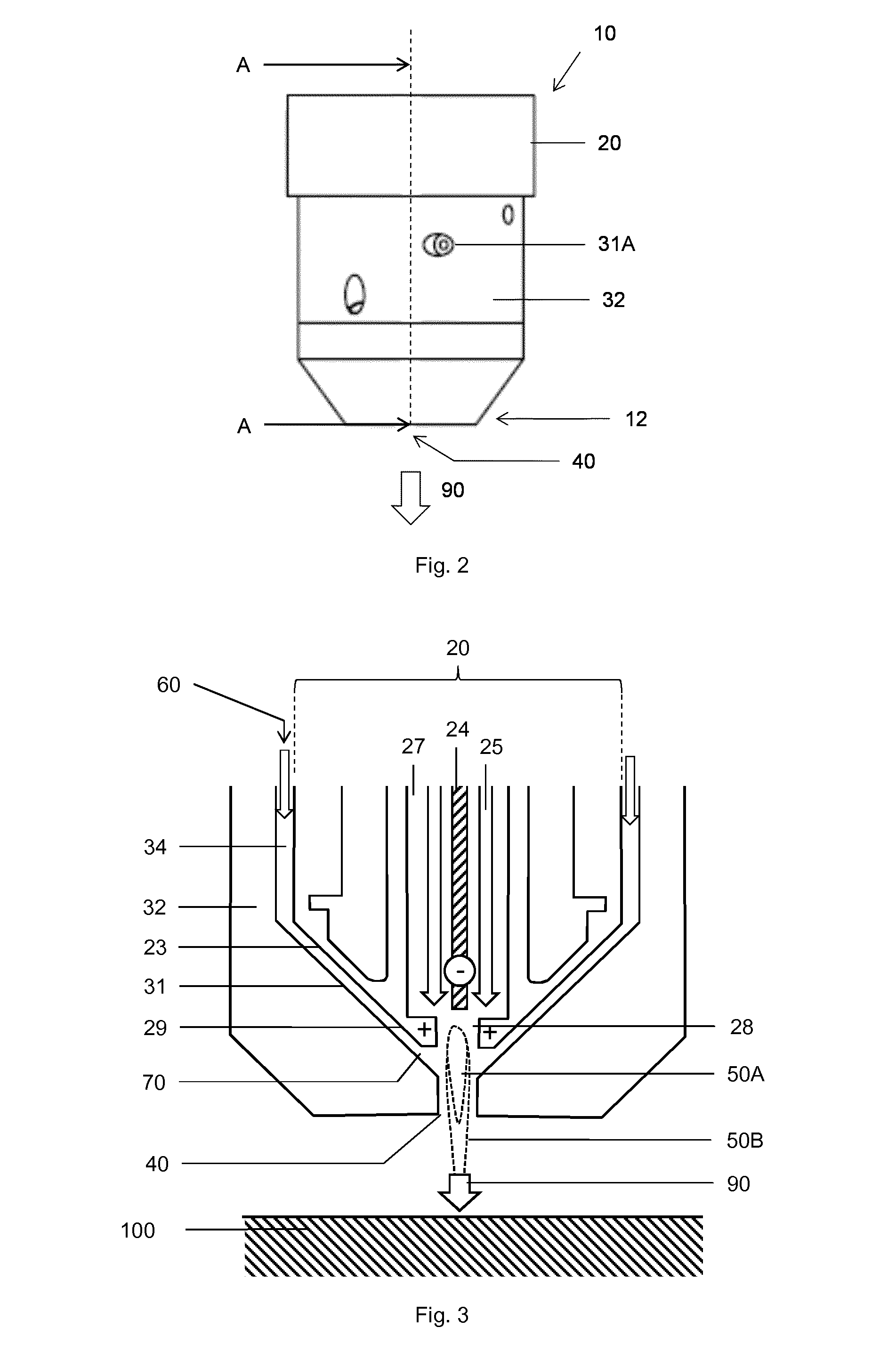
[0048]With reference to FIG. 1, an example thermal spray assembly 10 (shown in the assembled state, as a thermal spray device 10) for transforming precursor material 60 into a layer of deposited material joined to a substrate body (not shown);

[0049]comprising a plasma torch 20 and a feeder mechanism 30, configured such that the plasma torch 20 is capable of producing a plasma jet into a plasma region 50, to be occupied by the plasma jet and to extend from the plasma nozzle 28 in use. The feeder mechanism 30 is capable of guiding the precursor material 60 into the plasma in an open condition (as sown in FIG. 1) and comprises a guide chamber 34 and a moveable guide mechanism 32. The feeder mechanism 30 is configured such that the guide chamber 34 is capable of guiding the precursor material 60 to the feeder orifice 70, through which the precursor material 60 can move from the guide chamber 34 and enter the plasma jet in the plasma region 50 at a variable mean distance from the plasma ...


PUM


Abstract

A thermal spray assembly (10) for transforming precursor material (60) into a layer of deposited material joined to a substrate body. A plasma torch (20) produces a plasma jet from a plasma nozzle (28). A feeder mechanism (30) guides the precursor material (60) into the plasma jet in use and provides a feeder orifice (70) when in an open condition. The feeder mechanism comprises a guide chamber (34) and a moveable guide mechanism (32), and the guide chamber is capable of guiding the precursor material to the feeder orifice, through which the precursor material can move from the guide chamber and enter the plasma jet at a variable mean distance from the plasma nozzle (28) in response to movement of the guide mechanism (32).

Description

TECHNICAL FIELD[0001]This disclosure relates generally to thermal spray assemblies and methods of using them to deposit material on a substrate, particularly but not exclusively for depositing a hard layer onto a steel body, such as a tool for mining, earth boring or road milling.BACKGROUND ART[0002]International patent application, publication number WO / 2013 / 178550 discloses a method for making a construction comprising a steel substrate body coated with a layer of relatively harder material. The method may include providing a plurality of granules comprising iron (Fe), silicon (Si) and a source of carbon (C), in which the relative quantities of the Fe, Si and are selected such that the combination of the Fe, Si and C has a phase liquidus temperature of at most about 1,280 degrees Celsius; and depositing the granules onto the substrate body by means of a thermal spray assembly. The thermal spraying process will involve heating the granules to a temperature of at least about 1,350 d...

Claims


Application Information

Patent Timeline
IPC IPC(8): B05B7/22H05H1/42
CPCH05H1/42B05B7/226
Inventor KRENN, ANDREAS
Owner ELEMENT SIX GMBH
Why Eureka
Try Eureka