
Frequency limit circuit and DC-DC converter including the same

a technology of frequency limit circuit and converter, which is applied in the direction of dc-dc conversion, power conversion systems, instruments, etc., can solve the problems of degrading the performance and/or reliability of an entire system, and achieve the effect of efficiently limiting the operation frequency and efficiently reducing audible frequency noise and/or electromagnetic interferen

Active Publication Date: 2022-08-23
SAMSUNG ELECTRONICS CO LTD
View PDF14 Cites 0 Cited by
  • Summary
  • Abstract
  • Description
  • Claims
  • Application Information

AI Technical Summary

Benefits of technology

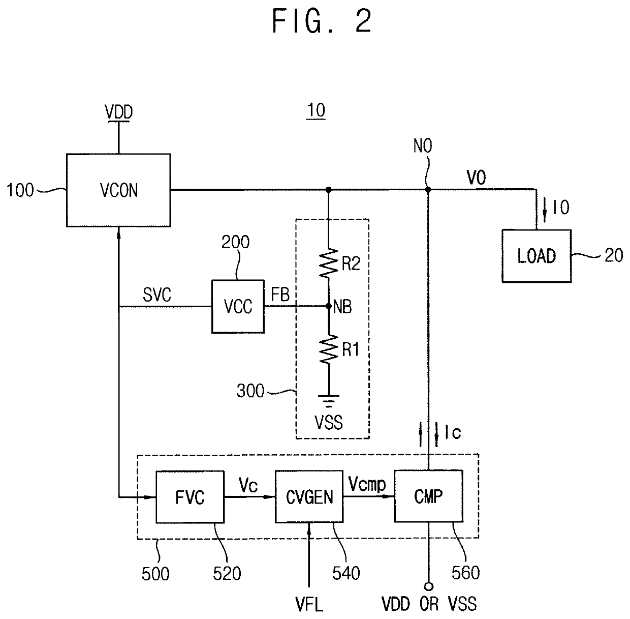
[0004]Some example embodiments may provide a frequency limit circuit and a DC-DC converter including the frequency limit circuit capable of more efficiently restricting an operation frequency of the DC-DC converter.
[0005]Some example embodiments may provide a method of controlling an operation of a DC-DC converter capable of more efficiently restricting an operation frequency of the DC-DC converter.
[0009]The frequency limit circuit, the DC-DC converter and the associated method according to example embodiments may more efficiently limit the operation frequency of the DC-DC converter and more efficiently reduce audible frequency noises and / or electromagnetic interference in devices and systems including the DC-DC converter by adjusting the compensation current through a negative feedback operation.

Problems solved by technology

For example, the operation frequency lower than an audible frequency may cause noises in particular components and degrade performance and / or reliability of an entire system in which the voltage converter is included.

Method used


Image

  • Frequency limit circuit and DC-DC converter including the same
  • Frequency limit circuit and DC-DC converter including the same
  • Frequency limit circuit and DC-DC converter including the same

Examples


Embodiment Construction

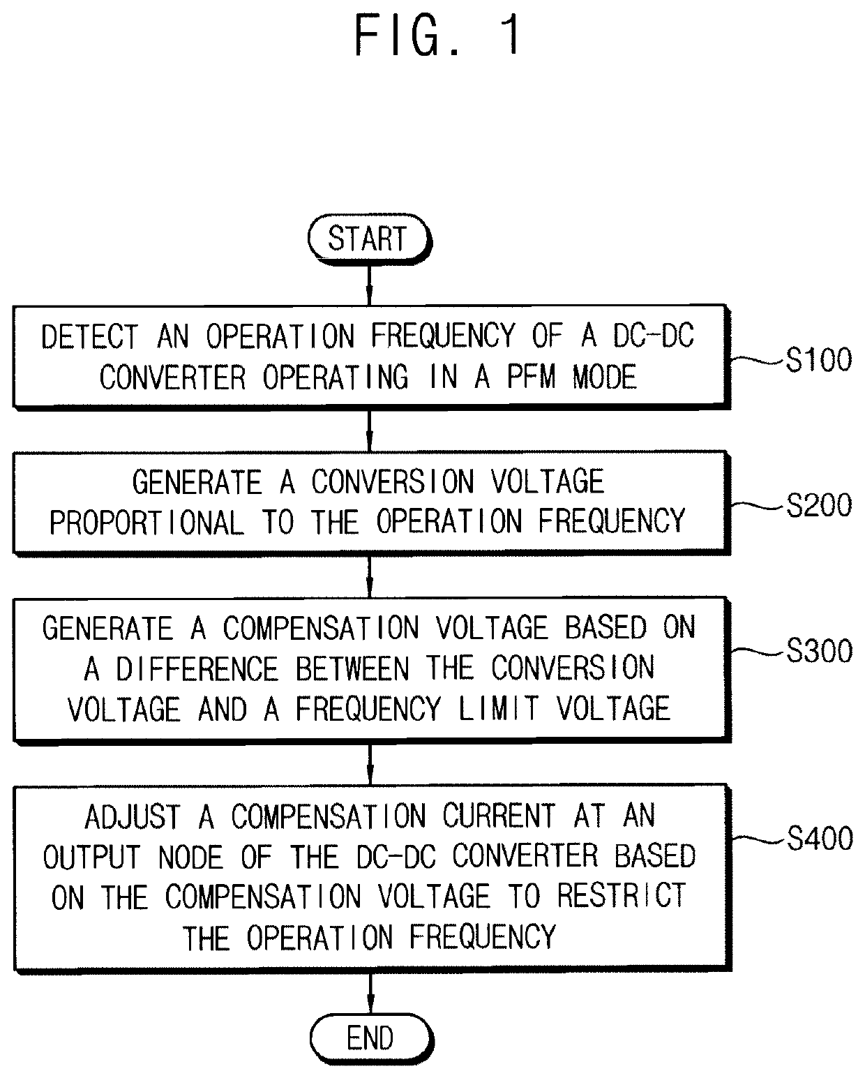
[0031]Various example embodiments will be described more fully hereinafter with reference to the accompanying drawings, in which some example embodiments are shown. In the drawings, like numerals refer to like elements throughout. The repeated descriptions may be omitted.

[0032]FIG. 1 is a flow chart illustrating a method of controlling an operation of a DC-DC converter according to example embodiments.

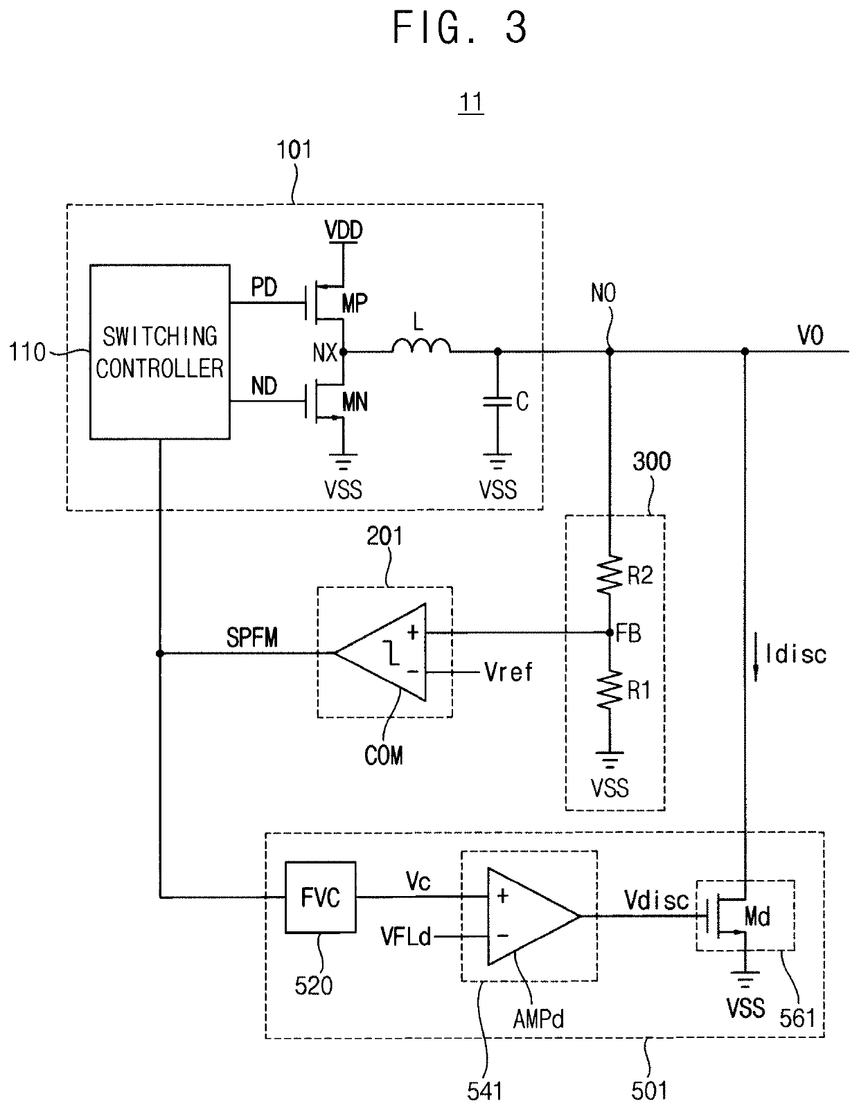
[0033]Referring to FIG. 1, an operation frequency of a direct current (DC)-DC converter operating in a PFM mode is detected (S100). In the PFM mode, the DC-DC converter may generate a PFM voltage control signal including pulses corresponding to the operation frequency and detect the operation frequency based on the PFM voltage control signal. Example embodiments of generating the PFM voltage control signal will be described below with reference to FIGS. 3 and 12.

[0034]A conversion voltage proportional to the operation frequency is generated (S200). Example embodiments of generating the...


PUM


Abstract

A frequency limit circuit includes a frequency-voltage converter, a compensation voltage generator and a compensator. The frequency-voltage converter generates a conversion voltage proportional to an operation frequency of the DC-DC converter based on a pulse-frequency modulation (PFM) voltage control signal indicating the operation frequency. The compensation voltage generator generates a compensation voltage based on a difference between the conversion voltage and a frequency limit voltage. The compensator adjusts a compensation current at an output node of the DC-DC converter based on the compensation voltage to restrict the operation frequency. The operation frequency of the DC-DC converter may be restricted efficiently by adjusting the compensation current through the negative feedback operation.

Description

CROSS-REFERENCE TO RELATED APPLICATION[0001]This U.S. non-provisional application claims priority under 35 USC § 119 to Korean Patent Application No. 10-2019-0173269, filed on Dec. 23, 2019, in the Korean Intellectual Property Office (KIPO), the disclosure of which is incorporated by reference herein in its entirety.BACKGROUND1. Technical Field[0002]Example embodiments relate generally to semiconductor integrated circuits, and more particularly to a frequency limit circuit and a DC-DC converter including the frequency limit circuit.2. Discussion of the Related Art[0003]A voltage converter, which converts a relatively high direct current (DC) voltage to a relatively low DC voltage, is typically employed to provide power to electronic devices. The voltage converter may be included in various devices and systems such as mobile devices, electric motor vehicles, etc. A voltage converter typically has high performance and high efficiency. For example, to rapidly charge various batteries, ...

Claims


Application Information

Patent Timeline
Patent Type & Authority Patents(United States)
IPC IPC(8): H02M3/158H02M1/08
CPCH02M3/158H02M1/08H02M3/1566H02M1/0032H02M3/156H02M1/0006
Inventor NAM, HYUNSEOK
Owner SAMSUNG ELECTRONICS CO LTD
Learn More