Modular magnetic assembly

a module and magnetic assembly technology, applied in the field of module magnetic assembly, can solve the problems of not fully up against the outer surface of the housing, custom-designed external magnet assembly, poor performance, etc., and achieve the effect of easy movement of the magnet into the out-of-use position and high susceptibility to magnetization

Active Publication Date: 2022-09-13
ADEY HLDG
View PDF14 Cites 0 Cited by
  • Summary
  • Abstract
  • Description
  • Claims
  • Application Information

AI Technical Summary

Benefits of technology

[0008]The magnetic belt assembly, when placed around a filter housing, creates a magnetic filter. Because the assembly is modular, a longer or shorter belt can be produced simply by using more or fewer modules. Therefore, magnetic filters of various different sizes can be made, without the need to manufacture large numbers of custom-moulded parts. Furthermore, any suitable vessel which is already connected into a central heating system circuit, for example a water and dirt separator, can effectively be upgraded to include a magnetic capture capability, simply by installing a magnetic belt assembly around the outside surface of the existing vessel. If the vessel to be upgraded is not already fitted with suitable valves and a drain port, these can easily be fitted on the inlet and outlet, where the vessel connects into the heating circuit, to allow the filter to be cleaned.
[0012]Because of the advantage of providing tightening means, it is envisaged that in most embodiments the joining (and tightening) means will be provided by a separate component, or possibly a pair of components, which is / are attached to end(s) of the assembled belt. However, by designing the modules in a suitable way, it may be possible to incorporate joining means into the modules, so that the belt can be assembled from multiple modules, wrapped around the filter body, and then the modules at the ends of the belt joined directly to each other. One way of doing this may be to provide adjustable tightening means on each module, for adjusting the spacing between adjacent modules. Each individual tightening means may require only a small amount of adjustability. The belt would be assembled with all of the tightening means on a loose setting, wrapped loosely around the outer surface of the filter body, and the modules at the ends of the belt joined directly together. The tightening means of each module can then be incrementally tightened, drawing the modules towards each other along the belt and around the filter body, to tighten the endless belt around the filter body and thereby retain it in place.
[0014]Preferably, a mechanism is provided for moving the magnet of each module, which provides a mechanical advantage at least when moving the magnet out of the in-use position into the out-of-use position. When the filter has been in operation for some time and magnetic particles have accumulated on the inside surface of the filter body, there will be significant magnetic attraction between the magnetic particles and the magnet of each module, pulling the magnet of each module towards the surface of the filter body. In order to easily move the magnet into the out-of-use position, some mechanical advantage is required. For example, the magnet may be mounted on a screw-threaded shaft. In one embodiment, the magnet is mounted on a carrier having an internally screw-threaded aperture, and an externally screw-threaded shaft is connected to an operating handle, so that when the operating handle is turned to screw the externally-threaded shaft into the internally-threaded aperture, the magnet is drawn towards the handle, and away from the filter body. When the operating handle is turned to unscrew the threaded shaft out of the threaded hole, the magnet will move away from the handle, towards the filter body. Preferably, a spring is provided to urge the magnet towards the filter body, so that when the magnet is moved away from the body, the action of the screw thread is acting against the spring.
[0017]Preferably, the hinge between adjacent modules is substantially in the form of a pin on one side of each module, and a barrel on the other side of each module. The pin of each module can be placed into the barrel of its adjacent module. The hinge ideally allows for enough pivoting to allow use of the same modules to form different lengths of belt for use with filter bodies of different sizes. In some embodiments it may be desirable to make the hinged joints as flexible as possible, for example to accommodate sharp corners or irregular shapes on the filter body. However, since most of the time it is envisaged that filter bodies will be close to cylindrical, in a preferred embodiment the hinged joint is restricted in flexibility, for example to allow pivoting between modules of no more than 90 degrees, 60 degrees, 45 degrees or 30 degrees in different variants. Restricting the range of movement makes the belt easier to handle during assembly and fitting, bearing in mind that the modules contain strong magnets which will interact with each other. If unrestricted movement is allowed between modules then extreme care must be taken to avoid modules snapping together, which may cause damage or even injury.

Problems solved by technology

One problem with this type of filter is that good performance relies on the magnets being held tightly against the outer surface of the housing.
Usually, the outer surface of the housing is curved, and this presents a particular problem with accurately positioning an external magnetic element.
Tolerances in the manufacture of the housing mean that even a custom-designed external magnet assembly, which is supposed to exactly match the external profile of the filter housing, may not in fact fit completely up against the outer surface of the housing.
Also, the need to create a range of filters for various different sized heating systems requires custom matching parts in each different size, driving up the cost of this type of filter.
However, these devices are not usually effective to remove magnetic debris, in particular because magnetic particles are too small to be caught in a mesh or sieve filter without making the mesh so fine that the device would clog quickly.

Method used


Image

  • Modular magnetic assembly
  • Modular magnetic assembly
  • Modular magnetic assembly

Examples


Embodiment Construction

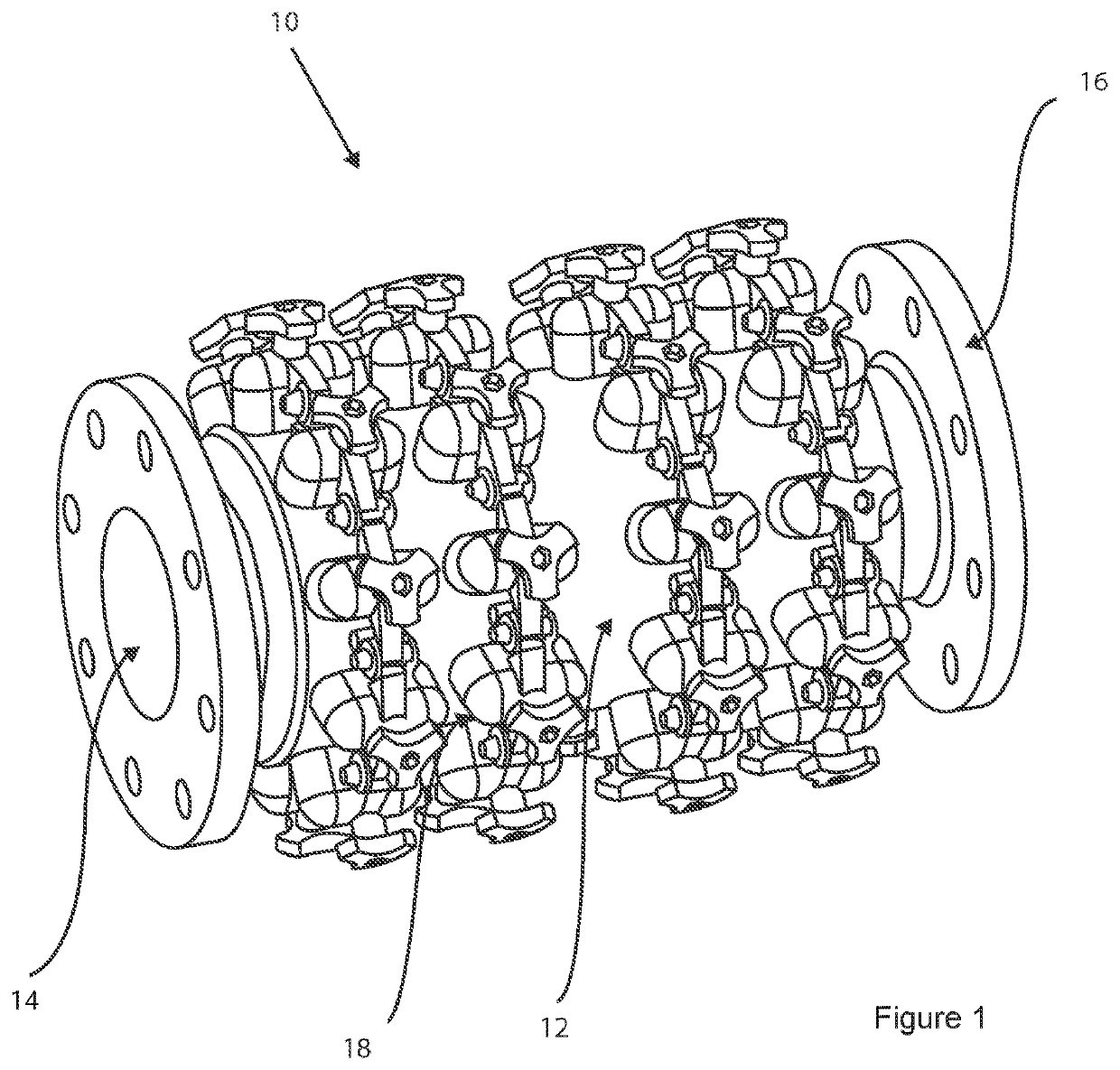
[0031]Referring firstly to FIG. 1, a magnetic filter for a central heating system is indicated generally at 10. The magnetic filter comprises a filter body 12, which is in the form of a substantially cylindrical section of stainless steel pipe. Inlet and outlet ports 14, 16 are provided for connection into a central heating system circuit. Flanges surround the inlet and outlet ports 14, 16, for fixing the magnetic filter 10 to similar flanges on central heating system pipework. The magnetic filter 10 may be produced in various different sizes, for fitting to central heating system pipework having a diameter from around 2 inches (50 mm) upwards.

[0032]This particular embodiment does not include any valves or a drain port, but these can be interposed between the filter body 12 and the central heating system pipework, using off-the-shelf valve and drain components.

[0033]This embodiment is designed for fixing to 2 inch (50 mm) pipework, the bore diameter at the inlet and outlet 14, 16 is...


PUM

PropertyMeasurementUnit
diameteraaaaaaaaaa
flexibleaaaaaaaaaa
mechanical advantageaaaaaaaaaa

Abstract

A magnetic filter (10) for a central heating system comprises a filter body (12) and an external magnetic assembly (18). The magnetic assembly is in the form of a belt which is made up of multiple modules. The modules may be identical to each other. The number of modules in the belt can be selected according to the size of the filter body, allowing various different sizes of filter to be produced from a small number of different parts. The filter body may be the body of an air-and-dirt separator, so that an existing air-and-dirt separator can be upgraded to include a magnetic capturing capability.

Description

CROSS-REFERENCE TO RELATED APPLICATIONS[0001]This patent application is a United States National Stage of International Patent Application No. PCT / EP2018 / 054230, filed Feb. 21, 2018, which in turn claims the benefit of Great Britain Patent Application No. GB1704015.5, filed Mar. 14, 2017. The entire disclosures of the above patent applications are hereby incorporated herein by reference.FIELD OF THE INVENTION[0002]The present invention relates to a modular magnetic assembly, in particular to a modular belt-like device which can be fitted around outer surfaces of filter housings of differing circumference.BACKGROUND TO THE INVENTION[0003]It is well known to provide magnetic filters in wet central heating systems, to remove magnetic particles which have become entrained in the flow of central heating system water. A magnetic filter typically comprises a housing with an inlet and an outlet, connected into a central heating system circuit so that central heating system water flows throu...

Claims


Application Information

Patent Timeline
Patent Type & Authority Patents(United States)
IPC IPC(8): B03C1/033B03C1/28C02F1/48
CPCB03C1/0332B03C1/288C02F1/482B03C2201/18B03C2201/28
Inventor DOWNIE, SIMON
Owner ADEY HLDG
Why Eureka
Try Eureka