Apparatus for detaching surgical blades

a technology for surgical blades and accessories, applied in the field of accessories for detaching surgical blades, can solve the problems of difficult tool manufacturing, unreliable use of two hands for blade removal, and device typically containing several movable parts

Active Publication Date: 2022-09-20
AUNEX PTY LTD
View PDF8 Cites 0 Cited by
  • Summary
  • Abstract
  • Description
  • Claims
  • Application Information

AI Technical Summary

Benefits of technology

[0017]In an embodiment, insertion of the tang into opening results in flexing of the spacing portion in a direction away from the tang thereby increasing the spacing between the tang and the heel portion of the blade.
[0018]Preferably, gradual insertion of the tang from the proximal end to the distal end of the opening results in positioning of the spacing portion in between the tang and the blade.

Problems solved by technology

Whilst specialized blade removal tools and devices are known in the prior art, one of the problems associated with such tools is that the operation of such known tools typically requires a user to use both their hands for removing the blade 20 from the handle 10.
The use of two hands for blade removal is considered to be generally unsafe and unreliable.
Another problem associated with the prior art tools and devices is that these devices typically include several movable parts.
The inclusion of a high number of movable parts can make manufacturing of the tool difficult.
WO2004093706A1 however the tool that is described therein is specifically designed to remove only one blade and then not to be used again and so is impractical in many situations.
Some of the other problems associated with currently known blade detachment devices relate to reliability of the prior art devices and high rates of failure due to excessive friction and jamming.

Method used


Image

  • Apparatus for detaching surgical blades
  • Apparatus for detaching surgical blades
  • Apparatus for detaching surgical blades

Examples


first embodiment

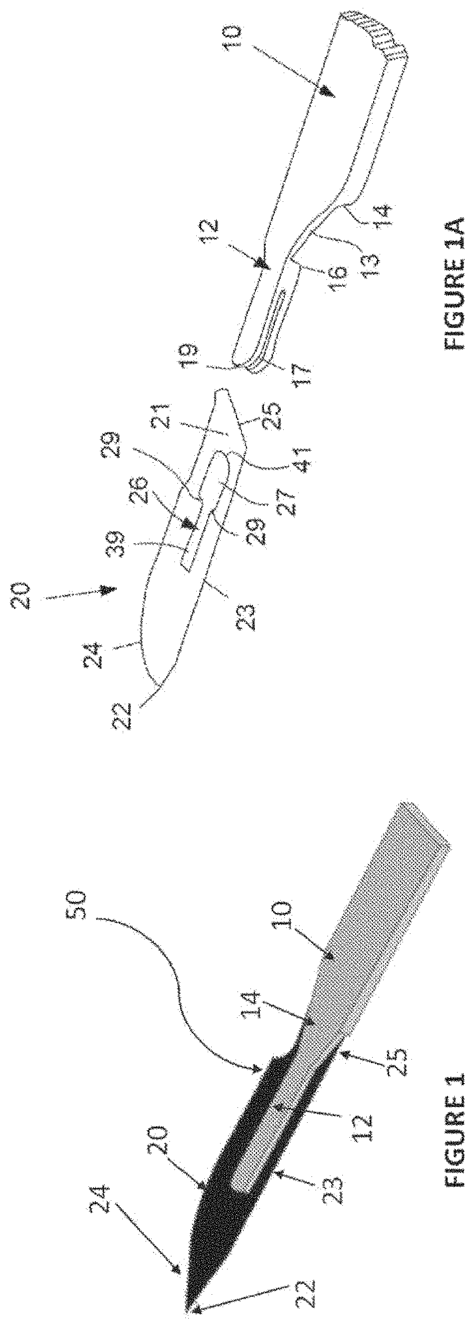
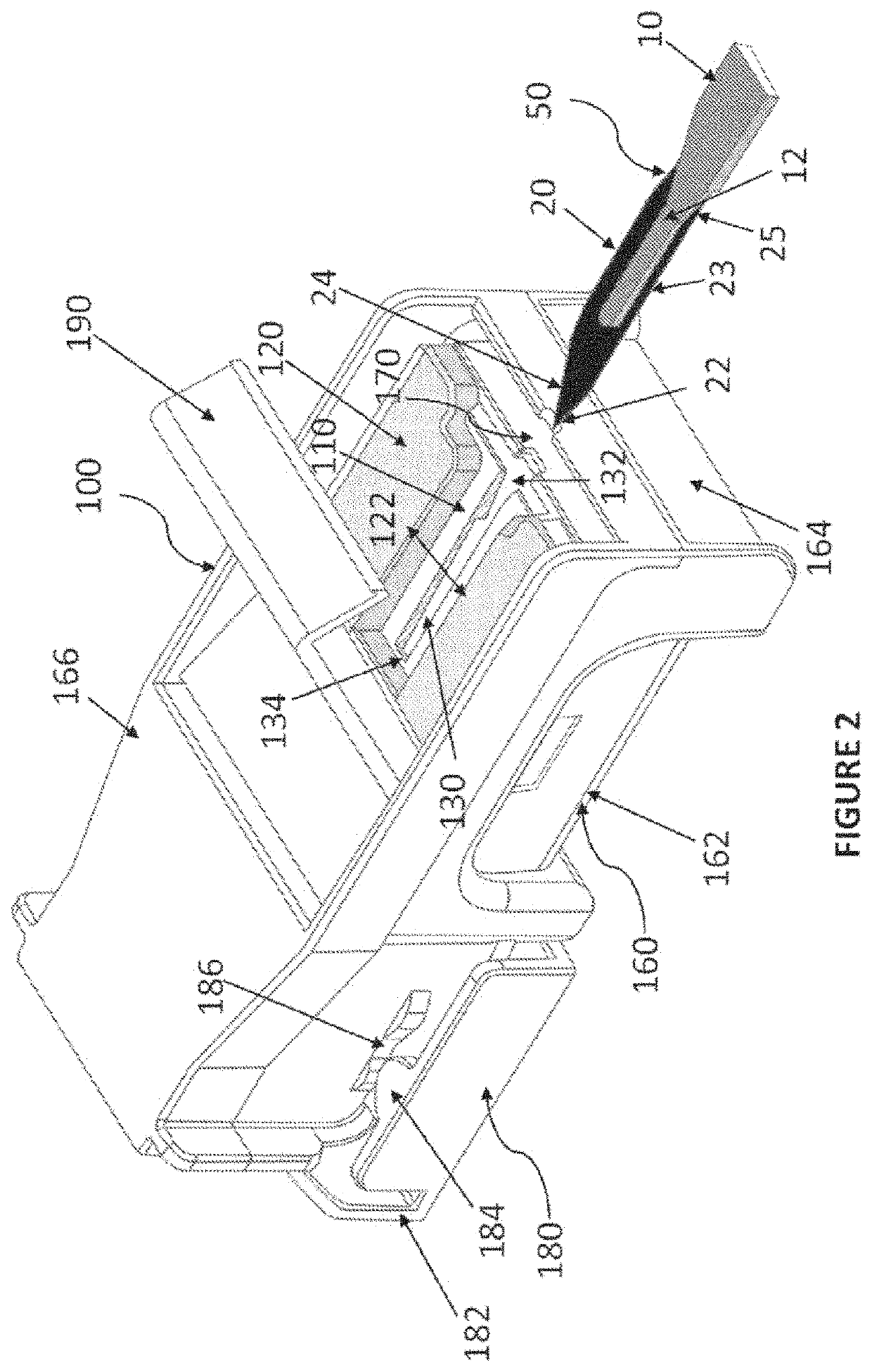
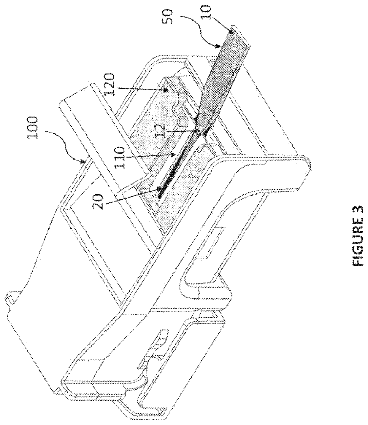
[0047]Referring to FIGS. 2 to 7, the present invention in the form of a blade removal device 100 is illustrated. The blade removal device 100 comprises a flexible blade detachment member 110 (preferably comprising a flexible polymeric material) that is arranged alongside a rigid polymeric backing plate 120. Specifically, the backing plate 120 is contiguously positioned above the flexible blade detachment member 110 in order to constrain the flexing of the blade detachment member 110 and only allow downward flexing of the detachment member 110 during use.

[0048]The detachment member 110 is formed with a longitudinal opening 130 that extends between a leading end 132 and a trailing end 134. The opening 130 is wide enough for the tang 12 to pass through but sufficiently narrow to obstruct passage of the blade 20. The opening or slot 130 is defined by the detachment member 110 and is shaped for positioning the tang 12 within the opening 130 which results in the mounted blade 20 being pos...

second embodiment

[0054]Referring to FIGS. 8 to 14, the present invention in the form of a blade removal device 200 is illustrated. The blade removal device 200 comprises a flexible blade detachment member 210 (preferably comprising a resilient polymeric material) that is arranged alongside a backing plate 220. Specifically, the backing plate 220 is positioned alongside the flexible blade detachment member 210 in a substantially parallel arrangement in order to constrain the flexing of the blade detachment member 210 and only allow downward flexing of the detachment member 210 during use.

[0055]The detachment member 210 defines an opening 230 that extends between a proximal end 232 and a distal end 234. The opening 230 is shaped for receiving the surgical blade 50, specifically the tang 12 of the handle 10. The opening or slot 230 is defined by the detachment member 230 and is shaped for positioning the tang 12 within the opening 230 which results in the mounted blade 20 being positioned adjacent belo...


PUM


Abstract

An apparatus for detaching a blade from a scalpel handle is provided. The blade has a cutting portion and a heel portion and is removably mounted on a tang of the scalpel handle. The apparatus has a flexible blade detachment member with a stepped portion for engaging the heel of the blade as the handle is withdrawn and a leading angled portion. A backing member is provided with the detachment member being arranged adjacent the backing member so that during use the detachment member flexes in only one direction, away from the mounting tang in response to force applied by the handle to the leading angled portion thereby causing the blade and the handle to be separated and detached relative to each other. Upon withdrawing the tang from the opening, the stepped portion engages the heel of the blade resulting in detachment of the blade from the tang.

Description

TECHNICAL FIELD[0001]The present invention relates generally to apparatus, devices, tools and systems directed to removing, used disposable surgical scalpel blades from scalpel handles and safely disposing of such contaminated blades.BACKGROUND[0002]Any references to methods, apparatus or documents of the prior art are not to be taken as constituting any evidence or admission that they formed, or form part of the common general knowledge.[0003]It is known that modern surgical scalpel blades are disposable, and are designed to fit a reusable handle to form a surgical knife. FIGS. 1 and 1A illustrate a commercially available surgical knife 50 which comprises a reusable handle 10 and disposable blade 20. The surgical blade 20 comprises a sharpened tip 22 and cutting edge 24 at the forward portion of the blade and a shank 23 extending to the rear portion 21 of the blade 20 which forms the heel 25 of the blade 20. The blade 20 is formed with a central elongate slot 26. Shoulders 29 of th...

Claims


Application Information

Patent Timeline
Patent Type & Authority Patents(United States)
IPC IPC(8): A61B17/3217A61B17/3213A61B50/36B65D25/10B65D83/10
CPCA61B17/3213A61B17/3217A61B50/362B65D25/10B65D83/10
Inventor QUEK, KIM SIA
Owner AUNEX PTY LTD
Why Eureka
Try Eureka