Heat dissipation assembly

a technology of heat dissipation assembly and heat dissipation chamber, which is applied in the direction of valve housing, sealing face pressure relieving device, semiconductor/solid-state device details, etc., can solve the problems of high-performance computer parts that require higher power consumption, affecting the operation fluency of the computer system, and increasing the operating temperature of high-power-consuming computer parts

Active Publication Date: 2022-09-20
GIGA BYTE TECH CO LTD
View PDF9 Cites 0 Cited by
  • Summary
  • Abstract
  • Description
  • Claims
  • Application Information

AI Technical Summary

Benefits of technology

[0005]The present invention provides a heat dissipation assembly that directs liquid diversion to reduce the probability of non-smooth flow due to excessive flow resistance.
[0016]Based on the above, the heat dissipation assembly of the present invention is provided with a valve structure on a partition structure separating a first flow path and a second flow path. The valve structure can be pushed away and closed with the magnitudes of liquid pressures in the first flow path and the second flow path. A part of fluid thus flows from a breach to the other flow path to achieve the effect of diversion, thereby reducing a fluid pressure in one of the flow paths and making liquid flow smoothly. Moreover, a part of heat carried by the liquid flowing through a heat source on an original flow path will be discharged out of a chamber in advance via the diversion effect of the valve structure, thereby accelerating partial fluid circulation and improving the heat dissipation efficiency.

Problems solved by technology

Today's computer gamers focus on good computer performance, and high-performance computer parts require higher power consumption.
In a high-speed computing environment, the operating temperature of high power consuming computer parts increases, which affects the operational fluency of a computer system.
Besides, the temperature of the heat source (such as the motherboard, the central processing unit or the display chip) is generally affected by the amount of cooling liquid flow.
The existing water-cooled heat dissipation assembly is usually limited by the space limitation of the heat source, such as uneven width of flow paths often occurs.
When liquid flows from a wider flow path to a narrower flow path, the problem of large flow resistance may be caused, thus affecting the heat dissipation efficiency of the heat dissipation assembly.

Method used


Image

  • Heat dissipation assembly
  • Heat dissipation assembly
  • Heat dissipation assembly

Examples


Embodiment Construction

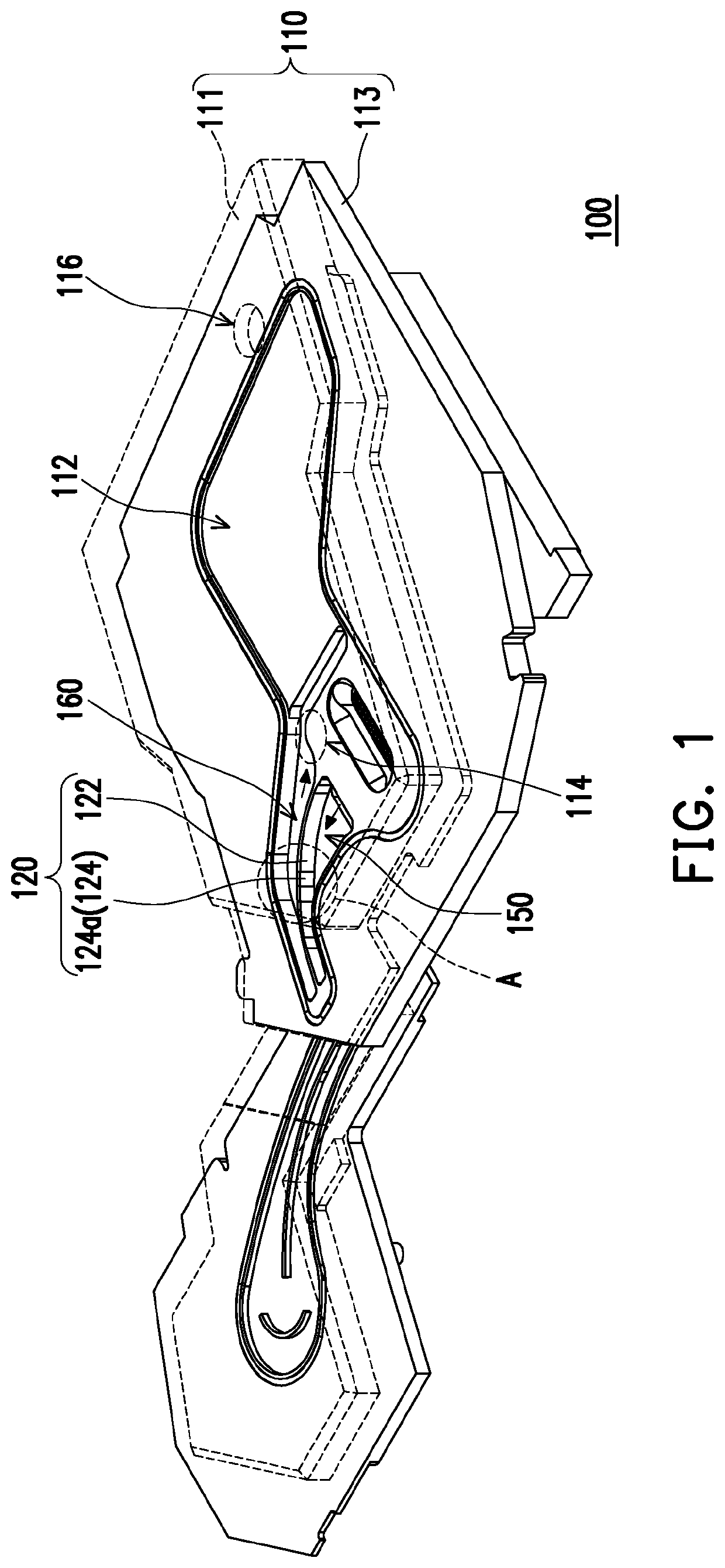
[0025]FIG. 1 is an appearance stereogram of a heat dissipation assembly according to an embodiment of the present invention. Referring to FIG. 1, a heat dissipation assembly 100 is adapted to dissipate heat from a heat source (not shown), where the heat source may be, for example, a central processing unit (CPU), a memory, a southbridge chip, a northbridge chip, or a graphic chip on a computer motherboard. In the present embodiment, the heat dissipation assembly 100 has a case 110 and a partition structure 120 disposed in the case 110. The case 110 has an upper housing 111 and a lower housing 113, a chamber 112 being formed between the upper housing 111 and the lower housing 113. The upper housing 111 includes a first water hole 114 and a second water hole 116. In the heat dissipation assembly 100 of FIG. 1, the upper housing 111 is indicated by a dashed line in order to clearly show the internal configuration of the case 110.

[0026]In the present embodiment, the partition structure ...


PUM


Abstract

A heat dissipation assembly includes a case and a partition structure. The case has a chamber. The partition structure includes a partition wall vertically disposed in the chamber to separate a first flow path and a second flow path in the chamber, and the partition wall has a breach and a valve structure disposed at the breach, wherein the valve structure covers the breach when the valve structure is not pushed open. When a fluid pressure existed in a section of one of the first flow path and the second flow path which is adjacent to the valve structure is greater than a fluid pressure existed in a section of the other one of the first flow path and the second flow path which is adjacent to the valve structure, the valve structure is pushed away to expose at least a part of the breach.

Description

CROSS-REFERENCE TO RELATED APPLICATION[0001]This application claims the priority benefit of Taiwan application Ser. No. 107147118, filed on Dec. 26, 2018. The entirety of the above-mentioned patent application is hereby incorporated by reference herein and made a part of this specification.BACKGROUND OF THE INVENTION1. Field of the Invention[0002]The present invention relates to a heat dissipation assembly, and in particular, to a heat dissipation assembly that utilizes liquid for heat conduction.2. Description of Related Art[0003]Today's computer gamers focus on good computer performance, and high-performance computer parts require higher power consumption. In a high-speed computing environment, the operating temperature of high power consuming computer parts increases, which affects the operational fluency of a computer system. A water-cooled heat dissipation assembly is one of the common heat dissipation methods, mainly absorbs the heat energy of a heat source (such as a motherbo...

Claims


Application Information

Patent Timeline
Patent Type & Authority Patents(United States)
IPC IPC(8): G05D15/00F16K17/00F16K11/16F16K27/12F16K39/04F28F13/08F28F27/02H05K7/20
CPCF16K17/003F16K11/168F16K27/12F16K39/045F28F13/08F28F27/02F28F2250/04H05K7/2039F28D2021/0028F28F3/12F28F2250/06H01L23/473H05K7/20281F28F2265/12F28D2021/0029
Inventor HUANG, SHUN-CHIHMAO, TAI-CHUANLIN, YI-JHEN
Owner GIGA BYTE TECH CO LTD
Why Eureka
Try Eureka