Support structure for automatic vehicle driving device

a technology of automatic vehicle driving and support structure, which is applied in the direction of vehicle arrangement, propulsion unit arrangement, structural/machine measurement, etc., can solve the problems of large vibration of automatic vehicle driving device during running test, large displacement due to load change, and difficulty in carrying the automatic vehicle driving device into and out of the vehicle interior

Active Publication Date: 2022-09-27
MEIDENSHA ELECTRIC MFG CO LTD
View PDF65 Cites 1 Cited by
  • Summary
  • Abstract
  • Description
  • Claims
  • Application Information

AI Technical Summary

Benefits of technology

[0010]The seat cushion generally has a flexible structure to ensure ride comfort. In comparison to this, the seat back has a firm structure to ensure load capacity (or withstand load) at a collision. Therefore, by adequately tightening the belt, a large tensile load can be applied. Further, as compared with a case where the automatic vehicle driving device is mounted on the seat cushion, the device can be rigidly or firmly supported. With this, vibrations of the device during the running test are reduced.
[0012]That is, as the seat back abutting part, both of the substantially U-shaped main frame and the substantially U-shaped sub frame abut against the seat back. It is therefore possible to prevent the seat back abutting part from being locally pressed against the seat back, and, for instance, this suppresses damage to a seat skin of the seat back.
[0014]In this configuration, the band-shaped lateral beam serving as the seat back abutting part comes into wide-surface-contact with the seat back. It is therefore possible to suppress damage to the seat skin of the seat back which is caused by being locally pressed. Further, because of the wide-surface-contact and suppressing of the damage to the seat skin, the tensile load of the belt can be set to be high, and the device is supported more firmly.
[0016]As a preferable aspect of the present invention, a lower edge of the seat back abutting part is positioned along seams of the seat skin which define a boundary between an upper pad portion and a lower pad portion of the seat back. Regarding the seat back of a recent driver's seat, in order to differentiate hardness of each section of the seat back, in many cases, the seat back is separated into the upper pad portion located close to shoulders of the seat back and the lower pad portion corresponding to the back, and the boundary between the upper pad portion and the lower pad portion is set to a height position that is not distinctly different from those of other driver's seats. Therefore, by forming the seat back abutting part so that its lower edge is positioned along the seams defining the boundary between the upper pad portion and the lower pad portion, positioning of the frame is easily done when mounting the automatic vehicle driving device in a vehicle interior. Further, since the seams are relatively recessed, the frame can be surely mounted.
[0017]As a specific aspect of the present invention, a belt loop through which the band-shaped belt passes is fixed to a middle portion in a longitudinal direction of each of a pair of right and left beams of the frame. In this configuration, positions of the belt are fixed, and a tensile force acts on wide areas of the beams of the frame, then an attitude of the frame becomes stable.
[0021]According to the present invention, the relatively heavy weight automatic vehicle driving device is not mounted on the seat cushion, but is fixed with the weight or load of the device being borne by the vehicle body floor located at a lower side of the front end of the seat cushion and the seat back having relatively high rigidity. Therefore, vibrations of the device, which are caused by elasticity of the seat cushion, during the running test are reduced. In addition, it is possible to pull or draw the automatic vehicle driving device sufficiently hard, thereby firmly fixing the automatic vehicle driving device.

Problems solved by technology

Because of this, a displacement due to a load change is large, and vibrations of the automatic vehicle driving device during the running test become large.
Therefore, it is hard to carry the automatic vehicle driving device into and out of a vehicle interior through a door opening of the vehicle.

Method used


Image

  • Support structure for automatic vehicle driving device
  • Support structure for automatic vehicle driving device
  • Support structure for automatic vehicle driving device

Examples


second embodiment

Next, an automatic vehicle driving device 301 of a second embodiment will be described.

[0279][General Configuration of Automatic Vehicle Driving Device 301 of Second Embodiment]

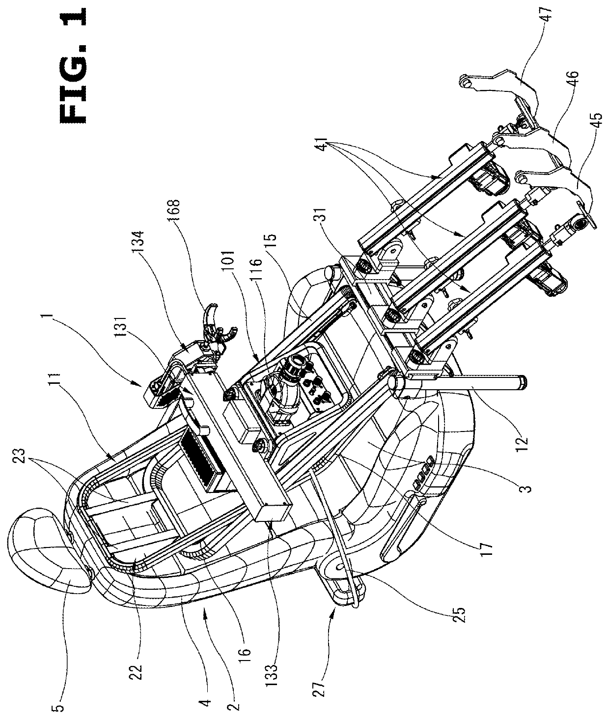
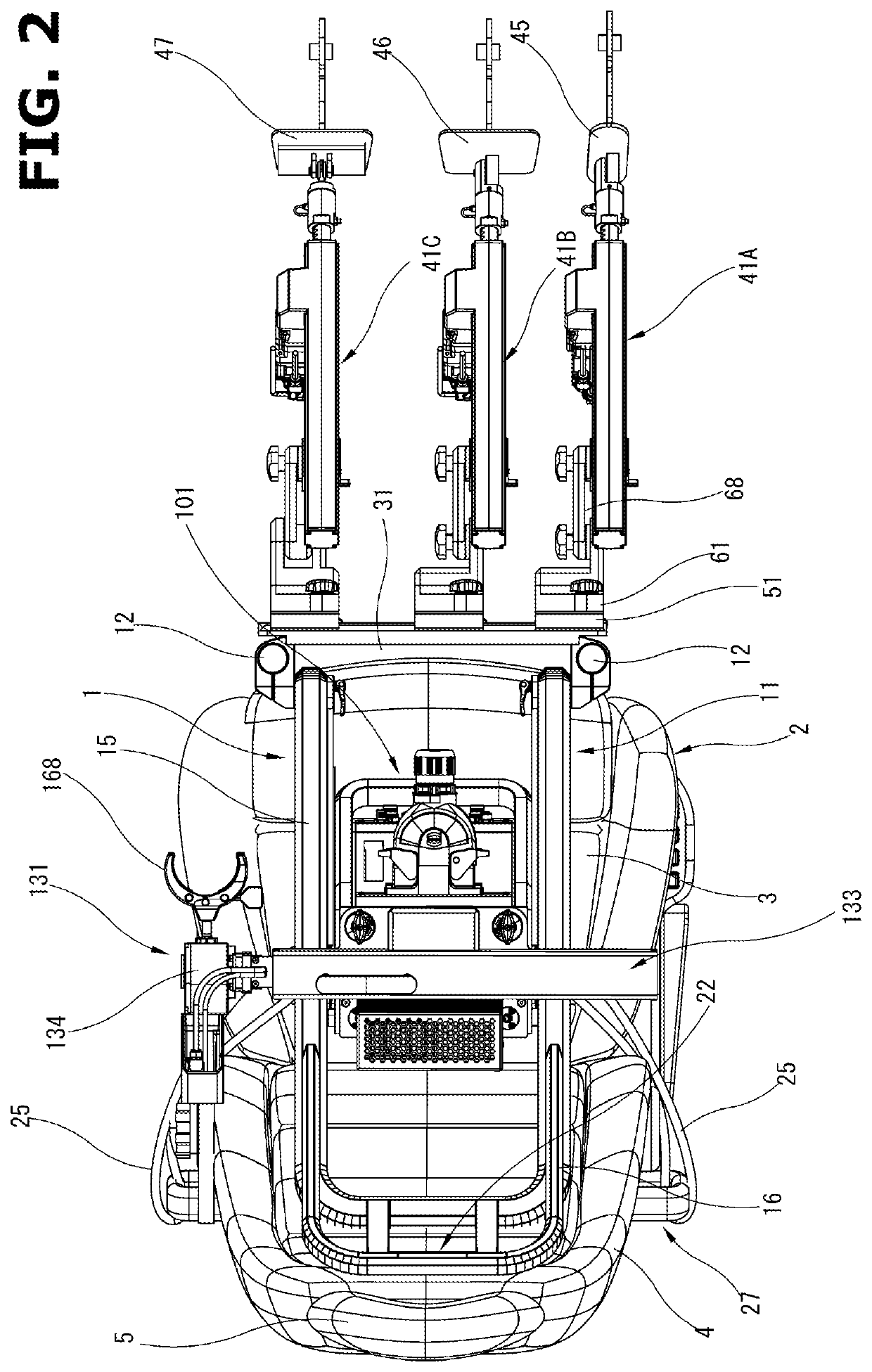
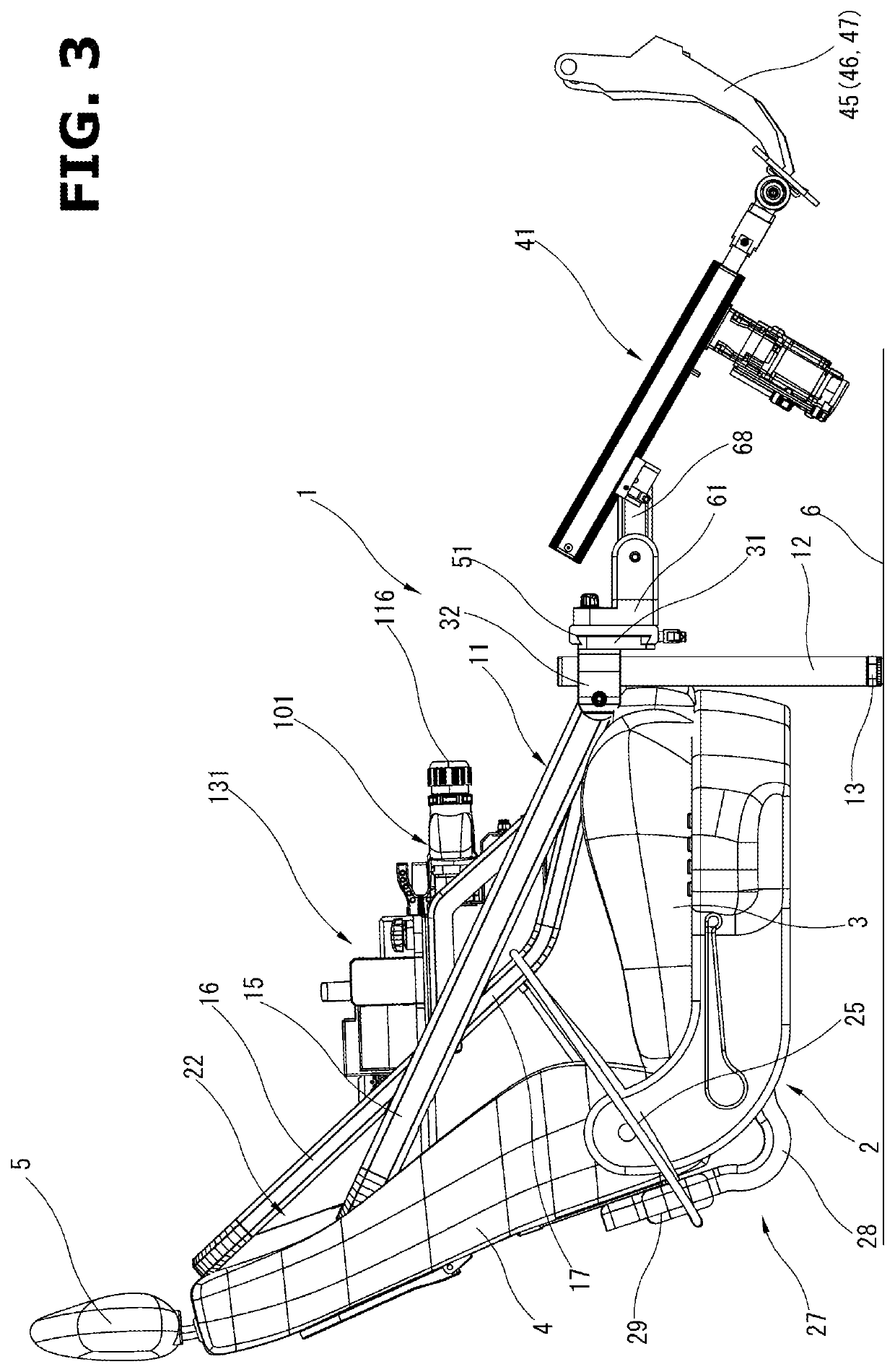
[0280]FIGS. 43 to 46 show a state in which the automatic vehicle driving device 301 of the second embodiment is mounted above a driver's seat 302 of a vehicle. FIGS. 47 to 51 show the automatic vehicle driving device 301 in its entirety with the device 301 dismounted from the vehicle. This automatic vehicle driving device 301 is used when carrying out a running test of the vehicle on a chassis dynamometer (not shown). The automatic vehicle driving device 301 performs a pedal operation of an accelerator pedal etc. and a shift-lever operation of a transmission by signals from an external controller placed outside the vehicle.

[0281]Here, as described later, the automatic vehicle driving device 301 of the present embodiment can be used for a vehicle with a manual transmission having a clutch pedal and for a vehic...


PUM


Abstract

An automatic vehicle driving device (1) including a transmission actuator unit (131) and pedal actuators (41) is supported as a whole by a frame (11) and legs (12). The frame (11) extends obliquely downward from a seat back abutting part (22) located at an upper end of the frame (11) toward a vehicle front side. The frame (11) is provided with the pair of legs (12) at a top end of the frame (11). The legs (12) extend downward along a front end of a seat cushion (3) and abut against the vehicle body floor (6). By tightening a belt (25) between the frame (11) and a seat support (27), the frame (11) is pulled obliquely downward and is firmly fixed. Since a flexible seat cushion (3) does not bear a load of the device (1), vibrations of the device (1) during a running test do not easily occur.

Description

TECHNICAL FIELD[0001]The present invention relates to an automatic vehicle driving device that performs a pedal operation etc., for instance, when carrying out a running test of a vehicle on a chassis dynamometer, and more particularly to a support structure of the automatic vehicle driving device in the vehicle.BACKGROUND ART[0002]When carrying out a running test of a vehicle on a chassis dynamometer, an automatic vehicle driving device that performs a pedal operation and a shift-lever operation of the vehicle in place of a driver is generally used.[0003]This type of automatic vehicle driving device is mounted on a driver's seat of the vehicle, and as disclosed in Patent Documents 1 and 2, many of the conventional automatic vehicle driving devices have a frame structured as a substantially L-shaped chair shape, and this frame is mounted on a seat cushion of the driver's seat, i.e. on a seat surface of the driver's seat, then the automatic vehicle driving device is fixed to the seat...

Claims


Application Information

Patent Timeline
Patent Type & Authority Patents(United States)
IPC IPC(8): B60R11/04G01M17/007B60R11/00B60K26/00
CPCB60R11/04G01M17/0072B60K26/00B60R2011/0012B60R2011/0059G01M17/007B60N3/00
Inventor KODAMA, AKIHIKOOKAZAKI, NOBUO
Owner MEIDENSHA ELECTRIC MFG CO LTD
Why Eureka
Try Eureka