
Absorbing apparatus

a technology of absorbing apparatus and absorbing unit, which is applied in the direction of shock absorbers, elastic dampers, bumpers, etc., can solve the problems of inability to absorb excess energy generated, inability of absorbing unit to dissipate so much energy, and insufficient protection of vehicles and/or cargo/passengers

Active Publication Date: 2022-09-27
AXTONE
View PDF15 Cites 0 Cited by
  • Summary
  • Abstract
  • Description
  • Claims
  • Application Information

AI Technical Summary

Benefits of technology

[0017]Preferably, the absorbing apparatus further comprises friction reducing elements arranged on the rear plate of the shock-absorbing unit and reducing friction between the absorbing apparatus and a vehicle structure or a coupler chamber.
[0021]By using the absorbent apparatus of the present invention, excess energy generated during an accident / collision can be easily dissipated. This affects to a large extent the safety of passengers as well as a cargo being transported.
[0022]During a collision, this excess energy is directed to a contact place between the energy absorbing element and the cutting unit. For this reason, the shock-absorbing unit is not loaded with the entire force generated at the moment of collision, whereby the level of its damage is significantly reduced. It also affects the safeguarding of train sets of the rail vehicle and their components, which in turn causes that costs of repairing the rail vehicle and the absorbing apparatus or the entire coupler after an accident are significantly reduced.
[0023]Furthermore, the use of the friction reducing element between the absorbing apparatus and the vehicle structure or the coupler chamber reduces wear of the vehicle structure or the coupler chamber.
[0024]The structure of the absorbing apparatus according to the present invention allows it to be assembled in a standard chamber of a coupler of ΓOCT or AAR standard or in a dedicated installation space.

Problems solved by technology

However, prior art solutions are unable to absorb excess energy generated at the time of a crash / collision.
The shock-absorbing unit is not able to dissipate so much energy, which leads to inadequate protection of a vehicle and / or cargo / passengers in the event of an accident.

Method used


Image

  • Absorbing apparatus
  • Absorbing apparatus
  • Absorbing apparatus

Examples


Embodiment Construction

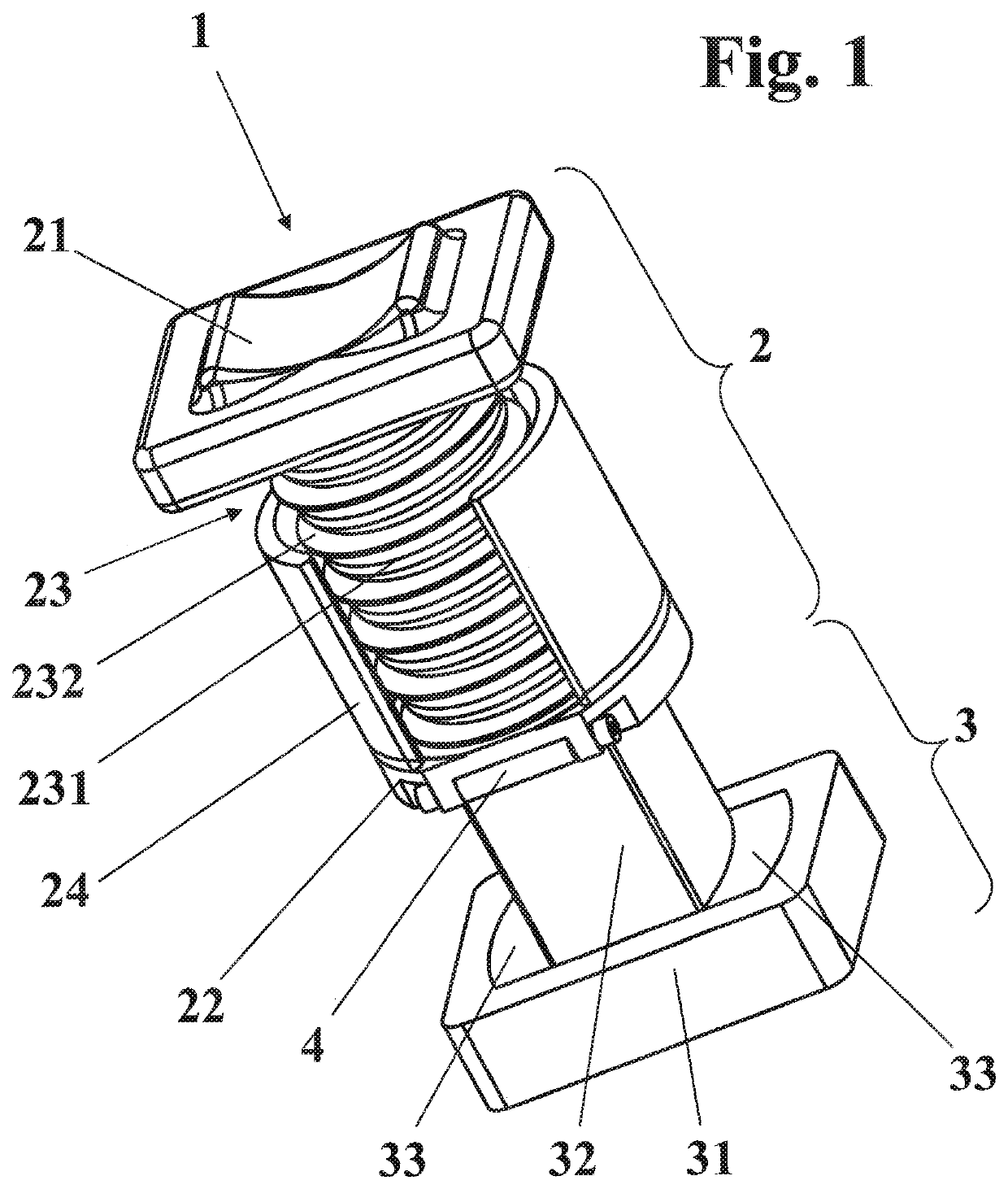
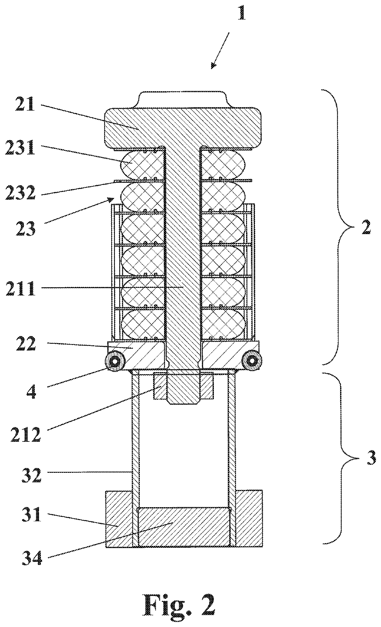
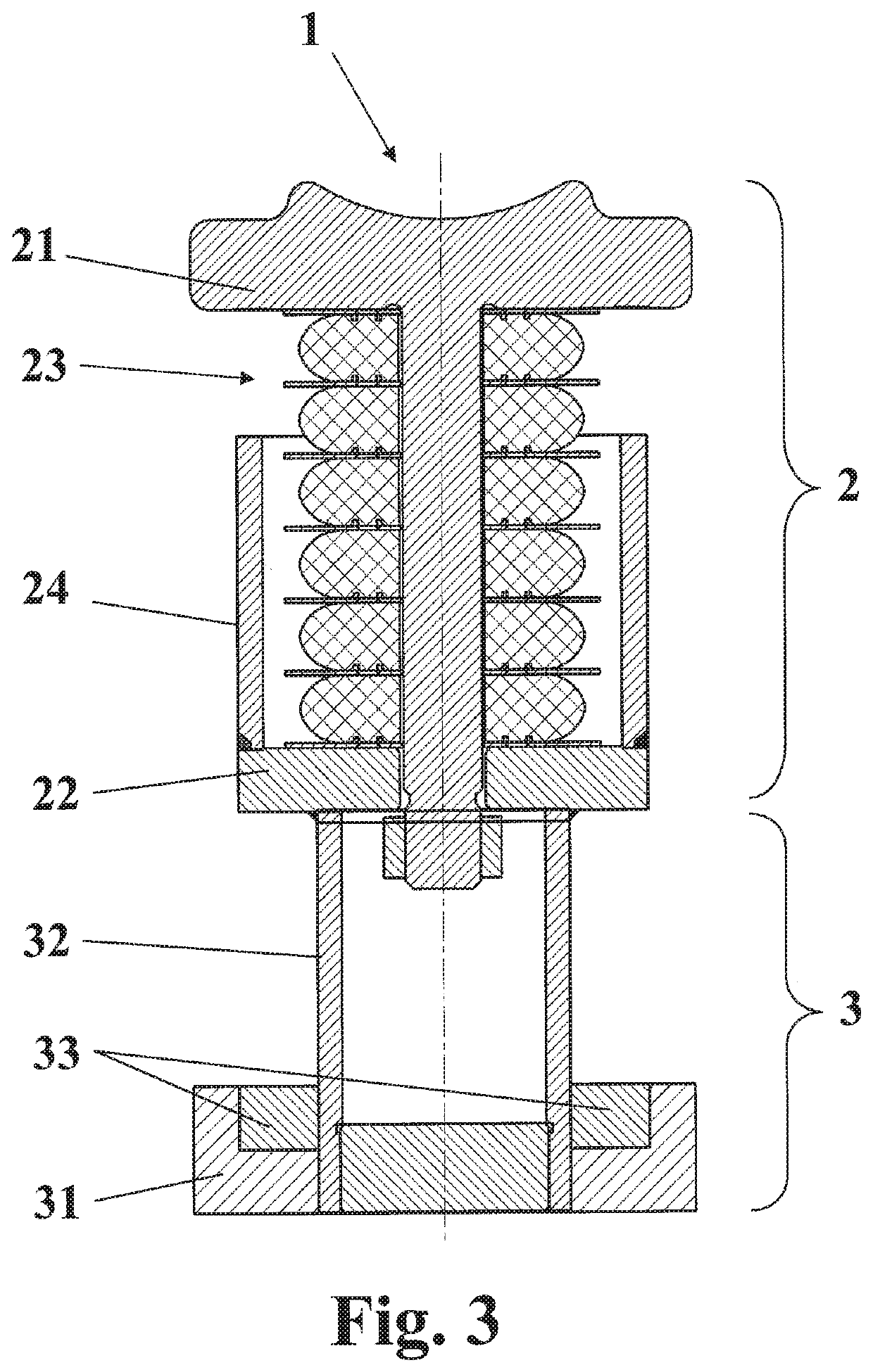
[0034]An absorbing apparatus 1 according to the invention comprises a shock-absorbing unit 2 mounted on / attached to a base 3.

[0035]The shock-absorbing apparatus 2 comprises a front plate 21, a rear plate 22 and a shock-absorbing core 23 arranged between the front plate 21 and the rear plate 22. The front plate 21 cooperates with a coupler head and a front abutment of a coupler chamber. The rear plate 22 can be made of a cast, a forging or welded elements. A mandrel 211, which passes through the rear plate 22, protrudes from the front plate 21 to connect all these elements into a single unit. Securing elements 212, which protect the rear plate 22 from falling from the mandrel 211, are located at an end of the mandrel 211. The shock-absorbing core 23 is superimposed on the mandrel 211. The mandrel 211 acts as a guiding element and maintains the desired operational direction of the absorbing apparatus 1. Another function of the mandrel 211 is to maintain the complex configuration of th...


PUM


Abstract

An absorbing apparatus includes a shock-absorbing unit that includes a front plate, a rear plate and a shock-absorbing core arranged between the front plate and the rear plate. The apparatus also includes a base connected to the rear plate of the shock-absorbing unit and having a rear plate, and a side shield surrounding at least partially the shock-absorbing core. One end of the side shield is connected to the front plate or the rear plate of the shock-absorbing unit, while the other end of the side shield is spaced-apart from the other of the front plate or the rear plate of the shock-absorbing unit. The base includes an energy absorbing element connected to the rear plate of the shock-absorbing unit and mounted in the rear plate of the base, while the rear plate of the base includes a cutting unit for cutting a surface of the energy absorbing element.

Description

CROSS-REFERENCE TO RELATED APPLICATIONS[0001]The present application is a U.S. National Stage filing under 35 U.S.C. § 371 of International Application PCT / PL2018 / 050044, filed Aug. 28, 2018 and entitled “ABSORBING APPARATUS”, which claims priority from Polish application App. Number P.422681 filed Dec. 28, 2018. The International Applications, including any appendices or attachments thereof, are incorporated by reference herein in its entirety.FIELD OF INVENTION[0002]The present invention relates to an absorbing apparatus, in particular a direction-acting absorbing apparatus for a rail-vehicle coupler, such as a central coupler, for example a SA3 type coupler, which absorbing apparatus is capable of absorbing excess energy generated during a collision.BACKGROUND OF INVENTION[0003]An absorbing apparatus for rail-vehicle couplers, used in a standard POCT or AAR installation and comprising a shock-absorbing unit mounted on a base is known from the prior art. The shock-absorbing unit c...

Claims


Application Information

Patent Timeline
Patent Type & Authority Patents(United States)
IPC IPC(8): B61G11/16B60R19/34B61G9/06B61G11/18B61G9/20F16F7/12B61G9/04
CPCB61G11/16B60R19/34B61G9/04B61G9/06B61G9/20B61G11/18F16F7/127
Inventor ZURAWSKI, GRZEGORZ
Owner AXTONE
Learn More