Multiphase flow mixed delivery method employing reciprocating driving performed by liquid in two chambers and device thereof

a technology of reciprocating driving and multi-phase flow, which is applied in the direction of gas/liquid distribution and storage, pipeline systems, mechanical equipment, etc., can solve the problems of large investment, complex process flow, and difficulty in operation and maintenan

Active Publication Date: 2022-09-27
G&F PUMP PET LED +1
View PDF28 Cites 2 Cited by
  • Summary
  • Abstract
  • Description
  • Claims
  • Application Information

AI Technical Summary

Benefits of technology

[0057]Compared with the prior art, the present disclosure has the following advantages:
[0059](2) The structural principle is simple, wherein the rising and falling liquid levels in the two containers act as a power piston, and there are no mechanical seal and lubrication problems. The liquid levels can be driven by an ordinary water pump. It does not have a complex structure as a multiphase flow mixed delivery pump of mechanical rotary type, and solves the problem of high water content to the pump.
[0060](3) The driving pump always works in pure liquid condition, and therefore ordinary mechanical seals can be used, which solves the multiphase sealing problem of multiphase flow mixed delivery pumps.

Problems solved by technology

There are disadvantages such as complex process flow, large investment, and difficulty in operation and maintenance.
There are many technical problems that need to be studied and resolved.
Multiphase flow mixed delivery pumps mainly rely on imports, which consume a lot of foreign exchange funds.
As a result, the efficiency of the pump drops drastically and even fails to run.
The mixing of oil, gas, and water in a multiphase flow is not uniform.
Friction parts such as rotor and side plate, screw and screw sleeve, rotor bearing, etc. are more severely worn due to lack of lubricating oil, causing sintering damage in the short term.
The biggest sealing problem of the multiphase flow mixed delivery pump is that the shaft end and the shaft in the pump chamber are dynamically sealed.
It faces a multiphase sealing problem.
Not only the sealing under pure liquid or pure gas conditions, but also the sealing problems under high-speed and variable-speed conditions.
The sealing problems of the multiphase flow mixed delivery pumps are an important issue in the design and research of the multiphase flow mixed delivery pumps at home and abroad.
The high-speed rotating rotor intensifies the separation of gas and liquid, resulting in greater load changes, resulting in violent vibration and displacement of the drive shaft, or even breakage.

Method used


Image

  • Multiphase flow mixed delivery method employing reciprocating driving performed by liquid in two chambers and device thereof
  • Multiphase flow mixed delivery method employing reciprocating driving performed by liquid in two chambers and device thereof

Examples


embodiment 1

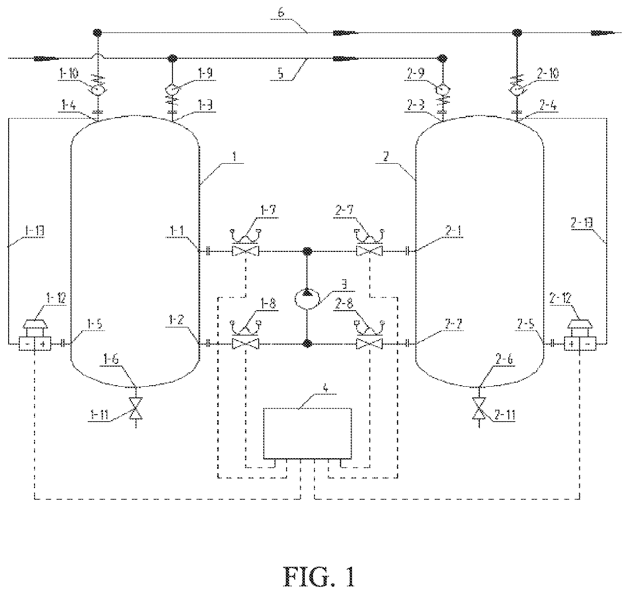
[0065]Refer to FIG. 1, a multiphase flow mixed delivery device employing reciprocating driving performed by a liquid in two chambers comprises a left container 1, a right container 2, a power pump 3, a data acquisition and control system 4, a solenoid valve group, a check valve group, an inlet manifold 5, and an outlet manifold 6.

[0066]An upper portion of the left container 1 is provided with a medium inlet and a medium outlet, an upper portion of the right container 2 is provided with a medium inlet and a medium outlet, which are a first medium inlet 1-3, a second medium inlet 2-3, a first medium outlet 1-4, and a second medium outlet 2-4. The first medium inlet 1-3 and the second medium inlet 2-3 are connected to the inlet manifold 5 through a first inlet check valve 1-9 and a second inlet check valve 2-9. The first medium outlet 1-4 and the second medium outlet 2-4 are connected to the outlet manifold 6 through a first outlet check valve 1-10 and a second outlet check valve 2-10....

embodiment 2

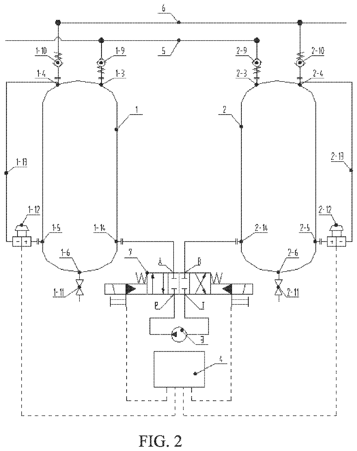
[0081]Refer to FIG. 1, a multiphase flow mixed delivery device employing reciprocating driving performed by a liquid in two chambers is provided. The structure of the device is basically the same as that of the multiphase flow mixed delivery device in Embodiment 1, except that a solenoid reversing valve 7 is used to replace the solenoid valve group in embodiment 1 (i.e. the first inlet solenoid valve 1-7, the first outlet solenoid valve 1-8, the second inlet solenoid valve 2-7, and the second outlet solenoid valve 2-8) to realize a function of switching inlet and outlet flow directions of the power pump 3. Due to the use of the solenoid reversing valve 7, the four port (the first circulating fluid inlet 1-1, the first circulating fluid outlet 1-2, the second circulating fluid inlet 2-1, the second circulating fluid outlet 2-2) on the left container 1 and the right container 2 are reduced to two ports (the first circulating fluid entrance 1-14 and the second circulating fluid entranc...


PUM


Abstract

A multiphase flow mixed delivery device employing reciprocating driving performed by a liquid in two chambers comprises a left container (1), a right container (2), a power pump (3), a data acquisition and control system (4), a solenoid valve group, a check valve group, an inlet manifold (5), and an outlet manifold (6). A vacuum suction chamber and a compression discharging chamber alternately formed by the two containers serve as a suction chamber and a discharging chamber of a multiphase mixed flow delivery pump. After gas in a liquid-gas mixture is separated in the container, the gas is compressed by a liquid, and is discharged out of the container. The power pump constantly operates in a pure liquid working condition, thereby eliminating the issue in which a liquid with a high gas content affects the power pump. The invention requires only an ordinary water pump to achieve mixed delivery of a multiphase flow, and the ordinary water pump can even serve as a vacuum pump and a compressor for pure gas and operate continuously. Also disclosed is a multiphase flow mixed delivery method using the multiphase flow mixed delivery device employing reciprocating driving performed by a liquid in two chambers.

Description

RELATED APPLICATIONS[0001]This application is a National Phase of PCT Patent Application No. PCT / CN2019 / 098320 having International filing date of Jul. 30, 2019, which claims the benefit of priority of Chinese Patent Application No. 201811286148.0 filed on Oct. 31, 2018. The contents of the above applications are all incorporated by reference as if fully set forth herein in their entirety.FIELD AND BACKGROUND OF THE INVENTION[0002]The present disclosure relates to oil and gas mixed delivery and natural gas well pressurized delivery devices in the field of oil production.[0003]The output of crude oil is mainly a mixture of oil, water and gas, and it also contains a small amount of sediment, which is a multiphase mixture. The traditional technology of oil and gas production and delivery in oil fields is to first separate oil, gas, and water, and then use oil pumps, water pumps, and compressors to deliver them separately. There are disadvantages such as complex process flow, large inve...

Claims


Application Information

Patent Timeline
Patent Type & Authority Patents(United States)
IPC IPC(8): F17D1/00F17D3/01F17D3/03F17D1/14
CPCF17D1/005F17D3/01F17D1/14F17D3/03
Inventor GUAN, TIANRI
Owner G&F PUMP PET LED
Why Eureka
Try Eureka