End assembly for welding device

a technology for welding devices and end assemblies, applied in shielding devices, shielding gas supply/evacuation devices, support devices, etc., can solve problems such as welding puddles, and achieve the effect of improving shielding and cooling of welding tips

Active Publication Date: 2022-10-04
ELCO ENTERPRISES
View PDF8 Cites 0 Cited by
  • Summary
  • Abstract
  • Description
  • Claims
  • Application Information

AI Technical Summary

Benefits of technology

[0004]The end assembly of the present invention is used with a welding device for GMAW. In one embodiment, the end assembly includes a gooseneck, a diffuser body, a contact tip and a nozzle. The components of the end assembly are secured together so as to share a common axis. The diffuser body features a number of passageways for allowing shielding gas to flow into an annular space between the diffuser body, contact tip and nozzle. In addition, the diffuser body features passageways extending toward the contact tip and communicates with a gas chamber. The gas chamber in turn provides gas to one or more passageways in the contact tip. In one embodiment, a plurality of tip passageways are arranged parallel to and around the central electrode bore of the contact tip. In another embodiment, the central electrode passageway of the tip is backboard at the base of the tip to provide clearance for gas flow to a series of transverse passageways through the nozzle tip. In both embodiments, the gas flow channels, combined with the gas flow around the outside annular surface of the nozzle tip, provide improved shielding and cooling of the welding tip.
[0005]Further still, the present invention relates to a contact tip for a welding device having a radiused or rounded convex curved first end, and a radiused or rounded second end with a center bore extending. The second end of the diffuser body has buttress threads with mate with buttress threads of the contact tip. The diffuser body has a radiused or rounded concave surface. When the contact tip is attached to the diffuser body, the mating concave and convex surfaces are brought into direct contact, providing excellent thermal and electrical conductivity between these components. In the first embodiment, the above-described tip gas flow channels are positioned directly adjacent to the central electrode bore so as not to interfere with the contact between the mating concave and convex surfaces of the contact tip and diffuser body. In the second embodiment, the contact tip features an enlarged electrode passageway at the base of the tip, with the bore at the entrance end of the contact tip radially inside the concave and convex surfaces of the diffuser body and contact tip. In both embodiments the diffuser body together with the contact tip form a gas flow chamber at the base of the contact tip which serves to distribute shielding gas to the flow passages of the contact tip.

Problems solved by technology

The heat of the arc melts the electrode and the workpiece in the region surrounding the arc, creating a weld puddle.

Method used


Image

  • End assembly for welding device
  • End assembly for welding device
  • End assembly for welding device

Examples


second embodiment

[0028]Now with reference to FIGS. 7, 8 and 9, an end assembly is shown, here designated by reference number 136. End assembly 136 utilizes diffuser body 94 identical to the prior embodiment. Differences in end assembly 136 relate to the configuration of contact tip 138. In this case, contact tip does not feature the parallel gas flow passages 120. Instead central nozzle bore 140 features an initial larger diameter section 142 and a distal section 144. Bore section 142 as a diameter substantially larger than the outside diameter of electrode 48 providing an annular space for the flow of shielding gas. However, distal bore section 144 closely conforms to the outside surface shape of the associated electrode 48 and provides electrical and thermal contact with the electrode. At the intersection of bore sections 142 and 144 a series of cross bores 146 are provided. In a preferred embodiment cross bores 146 are perpendicular to the longitudinal axis of the nozzle and a pair are provided w...

first embodiment

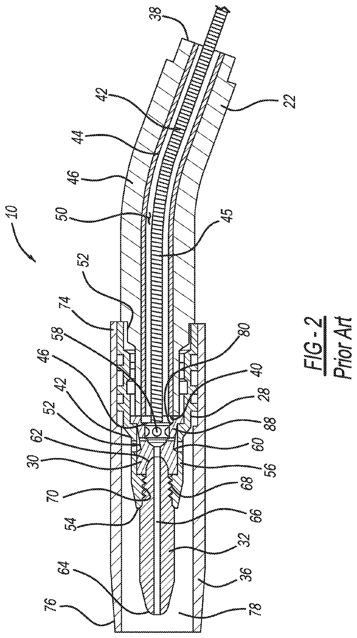
[0030]FIG. 7 shows and assembly 36 with wire guide 45 installed. As shown wire guide 45 is seated against the end surface of blind bore 122. This configuration would also be used in end assembly 92. As shown, bore 111 has a larger diameter than the outside diameter of wire guide 45. Also, where wire guide 45 abuts the blind end of bore 111, bores 124 are positioned outside the outer diameter of the wire guide providing for the flow path of shielding gas into chamber 128.

[0031]FIG. 8 shows in drawn lines the flow of shielding gas through and assembly 136. As shown, shielding gas is initially provided to the inside bore 111 of diffuser body 94. A portion of the gas flow flows radially out of bores 112. Another portion of the flow travels toward tip 138, flowing through offset bores 124 into chamber 128 and into the radial clearance provided between the enlarged bore section 142 and electrode 48. This flow travels along contact tip 138 until it reaches the point of intersection with cr...


PUM

PropertyMeasurementUnit
outer diameteraaaaaaaaaa
bore diameteraaaaaaaaaa
currentaaaaaaaaaa

Abstract

An end assembly for use with a welding device having a contact tip, a diffusor body, and a gooseneck. The contact tip has a convex end surface that contacts and mates with a concave end of the diffuser body. The diffuser body forms a blind bore forming central web and a series of passageways. A longitudinal passageway segment is formed in the contact tip parallel with the central longitudinal electrode bore of the contact tip. A second passageway segment joins the first longitudinal passageway segment. When the contact tip is affixed to the diffuser body, a chamber is formed at the base of the contact tip communicating with the diffuser body passageways. Shielding gas that flows into the diffuser body passes through the web passageways into the chamber and through the first and second passageways of the contact tip to provide shielding gas to the weld site and cool the contact tip during welding operations.

Description

FIELD OF THE INVENTION[0001]The present invention relates to an end assembly for use in a welding device. In particular, the present invention relates to end assembly for controlling the flow of gas during welding.BACKGROUND[0002]Metal Inert Gas (MIG) welding also referred to as “wire-feed” or Gas Metal Arc Welding (GMAW) utilizes heat from an electrical arc to melt a consumable electrode to form a weld on a workpiece. A MIG welding system typically includes a power supply, a gas supply and an electrode supply connected to a welding device or welding gun. A ground cable is used to connect the workpiece to the power supply. The welding device generally includes a handle, a gooseneck and an end assembly. The welding system can be automatic or semi-automatic and may be manually or robotically controlled. The electrode and gas are coupled through a conduit in the handle and the gooseneck to the end assembly of the welding device. The electrode extends through the contact tip of the end ...

Claims


Application Information

Patent Timeline
Patent Type & Authority Patents(United States)
IPC IPC(8): B23K9/29B23K9/32B23K9/173B23K9/10B23K9/16
CPCB23K9/295B23K9/325B23K9/1006B23K9/164B23K9/173
Inventor COOPER, EDWARD L.
Owner ELCO ENTERPRISES
Why Eureka
Try Eureka