Sensor system, sensor module, and lamp device

a technology of sensor modules and lamp devices, applied in the field of sensor modules, lamp devices, and sensor systems, can solve problems such as the inability to obtain desired images

Active Publication Date: 2022-10-11
KOITO MFG CO LTD
View PDF47 Cites 7 Cited by
  • Summary
  • Abstract
  • Description
  • Claims
  • Application Information

AI Technical Summary

Benefits of technology

[0020]Therefore, even if the number of types of sensors to be mounted on the vehicle increases, it is possible to reduce the burden of works for adjusting the sensing reference positions of the plural types of sensors relative to the vehicle.
[0054]According to such a configuration, the processing of the information sensed by the first sensor and the second sensor can be at least partially assigned to the controller of the sensor module. As a result, the control load of the controller mounted on the vehicle can be reduced.

Problems solved by technology

If the light emitted from the head lamp enters the field of view of the camera, a desired image may not be obtained.

Method used


Image

  • Sensor system, sensor module, and lamp device
  • Sensor system, sensor module, and lamp device
  • Sensor system, sensor module, and lamp device

Examples


Embodiment Construction

[0066]Examples of embodiments will be described below in detail with reference to the accompanying drawings. In each of the drawings used in the following descriptions, the scale is appropriately changed in order to make each of the members have a recognizable size.

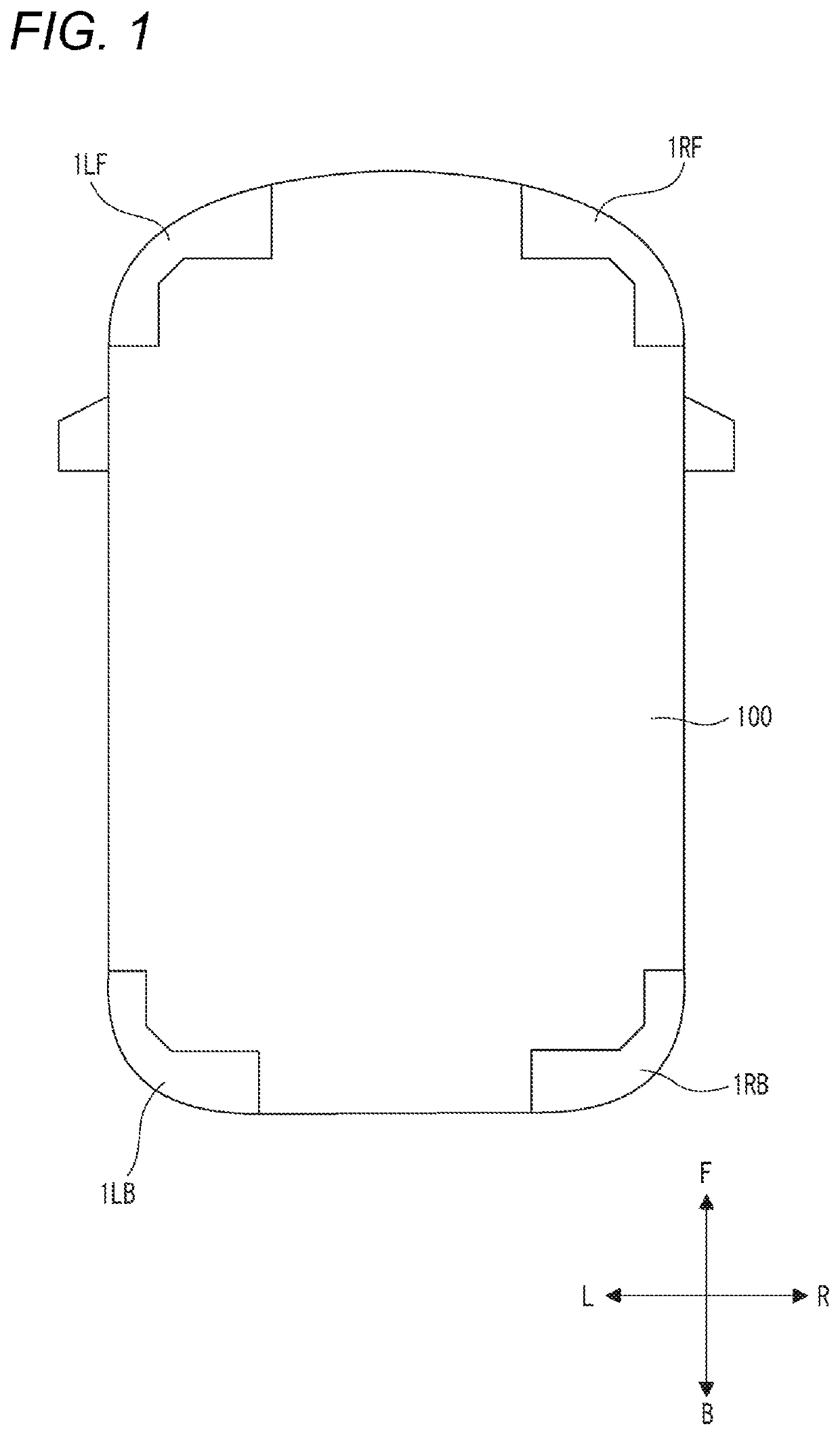
[0067]In the accompanying drawings, an arrow F represents a forward direction of the illustrated structure. An arrow B represents a rearward direction of the illustrated structure. An arrow L represents a leftward direction of the illustrated structure. An arrow R represents a rightward direction of the illustrated structure. The terms of “left” and “right” used in the following descriptions indicate the left-right directions as viewed from the driver's seat. In the accompanying drawings, the term “up-down direction” corresponds to the direction perpendicular to the drawing sheet.

[0068]As illustrated in FIG. 1, a left front sensor system 1LF according to a first embodiment is mounted on a left front corner of a vehicle 10...


PUM


Abstract

A LiDAR sensor (41) is configured to sense information of an outside of a vehicle. An ultrasonic sensor (42) is configured to sense information of the outside of the vehicle in a different manner from the LiDAR sensor (41). A first bracket (43) supports the LiDAR sensor (41) and the ultrasonic sensor (42). A first sensor actuator (44) is configured to adjust a sensing reference position of the LiDAR sensor (41) relative to the first bracket (43). A second sensor actuator (45) is configured to adjust a sensing reference position of the ultrasonic sensor (42) relative to first bracket (43). A first bracket actuator (46) is configured to adjust at least one of a position and a posture of the first bracket (43) relative to the vehicle.

Description

TECHNICAL FIELD[0001]The presently disclosed subject matter relates to a sensor system to be mounted on a vehicle.[0002]The presently disclosed subject matter also relates to a sensor module mounted on a vehicle, and a lamp device including the sensor module.BACKGROUND ART[0003]In order to realize a self-driving technique of a vehicle, sensors for obtaining external information of the vehicle shall be mounted on a vehicle body. Different types of sensors may be used to more accurately obtain the external information. As such sensors, a camera and a LiDAR (Light Detection and Ranging) sensor can be exemplified (see Patent Document 1, for example).[0004]Patent Documents 2 and 3 disclose a configuration in which a camera is disposed in a lamp chamber of a head lamp. The head lamp lights an area ahead of the vehicle. The camera captures an image of an area ahead of the vehicle. If the light emitted from the head lamp enters the field of view of the camera, a desired image may not be obt...

Claims


Application Information

Patent Timeline
Patent Type & Authority Patents(United States)
IPC IPC(8): G01S17/86G01S15/86G01S17/931B60Q1/00G01S7/521G01S17/08
CPCG01S17/86B60Q1/0023G01S7/521G01S15/86G01S17/08G01S17/931G01S15/931G01S17/42G01S7/4813G01S13/931G01S15/08G01S15/42G01S13/862G01S13/865G01S13/867G01S13/87G01S2013/93277G01S2013/93272G01S2013/93271G01S2015/937G01S7/027
Inventor YAMAMOTO, TERUAKIKASABA, YUSUKEHORI, TAKASHIFUSHIMI, YOSHIAKI
Owner KOITO MFG CO LTD
Why Eureka
Try Eureka