Systems and methods for temporally consistent depth map generation

a technology of depth map and system, applied in image analysis, image enhancement, instruments, etc., can solve the problems of user creating many challenges, user affecting the accuracy of depth perception, etc., to achieve the effect of improving temporal consistency

Active Publication Date: 2022-11-01
MICROSOFT TECH LICENSING LLC
View PDF12 Cites 0 Cited by
  • Summary
  • Abstract
  • Description
  • Claims
  • Application Information

AI Technical Summary

Benefits of technology

[0019]As described herein, at least some disclosed embodiments are operable to facilitate improved temporal consistency of the first depth map with the second depth map, and overall depth map quality.

Problems solved by technology

The process of using images captured by world-facing cameras to provide three-dimensional views of a real-world environment to a user creates many challenges.
Thus, directly providing the images captured by the stereo cameras to the user's eyes would cause the user to perceive the real-world environment incorrectly.
In another example, a difference in the spacing between the user's eyes and the spacing between the stereo cameras can cause the user to perceive real-world objects with incorrect depth.
However, calculating and processing depth information based on a stereo pair of images, particularly when addressing the parallax problem, is associated with many challenges.
For example, performing stereo matching to generate a depth map based on a stereo pair of images is a computationally expensive and / or time-consuming process.
In some instances, the complexity of a depth calculation is a product of the number of pixels in the image frames and the number of disparity calculations to be performed.
Thus, conventional mixed-reality systems may struggle to generate depth maps without significant latency, particularly where the underlying stereo pair of images has high image resolution.
The latency in calculating depth maps also delays operations that rely on depth information (e.g., parallax error correction), resulting in a poor user experience.
The lack of quality in depth maps generated by conventional stereo matching algorithms can degrade the smoothness and / or precision of a parallax-corrected images displayed to the user.
Furthermore, temporal inconsistencies often arise under conventional stereo matching algorithms.
Under conventional stereo matching algorithms, discrepancies often exist in the depth information for real-world objects that are represented in sequentially generated depth maps based on sequentially captured stereo pairs of images that were captured at different user poses (even for slight variations in user pose).
Such discrepancies, or temporal inconsistencies, can give rise to artifacts (e.g., depth flickers) from frame to frame in parallax-corrected images displayed to the user.

Method used


Image

  • Systems and methods for temporally consistent depth map generation
  • Systems and methods for temporally consistent depth map generation
  • Systems and methods for temporally consistent depth map generation

Examples


example method (

Example Method(s) for Temporally Consistent Depth Map Generation

[0194]The following discussion now refers to a number of methods and method acts that may be performed. Although the method acts may be discussed in a certain order or illustrated in a flow chart as occurring in a particular order, no particular ordering is required unless specifically stated, or required because an act is dependent on another act being completed prior to the act being performed.

[0195]FIG. 10 illustrates an example flow diagram 1000 that depicts various acts associated with methods for generating temporally consistent depth maps. The discussion of the various acts represented in flow diagram 1000 includes references to various hardware components described in more detail with reference to FIGS. 2 and 12.

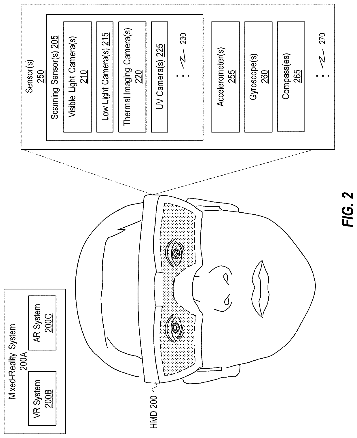
[0196]The first illustrated act is an act of obtaining a first stereo pair of images at a first timepoint (act 1002). Act 1002 is performed, in some instances, utilizing scanning sensor(s) 205 of an HMD ...


PUM


Abstract

Systems and methods are provided for performing temporally consistent depth map generation by implementing acts of obtaining a first stereo pair of images of a scene associated with a first timepoint and a first pose, generating a first depth map of the scene based on the first stereo pair of images, obtaining a second stereo pair of images of the scene associated with at a second timepoint and a second pose, generating a reprojected first depth map by reprojecting the first depth map to align the first depth map with the second stereo pair of images, and generating a second depth map that corresponds to the second stereo pair of images using the reprojected first depth map.

Description

BACKGROUND[0001]Mixed-reality systems, including virtual-reality and augmented-reality systems, have received significant attention because of their ability to create truly unique experiences for their users. For reference, conventional virtual-reality (VR) systems create a completely immersive experience by restricting their users' views to only a virtual environment. This is often achieved through the use of a head-mounted device (HMD) that completely blocks any view of the real world. As a result, a user is entirely immersed within the virtual environment. In contrast, conventional augmented-reality (AR) systems create an augmented-reality experience by visually presenting virtual objects that are placed in or that interact with the real world.[0002]As used herein, VR and AR systems are described and referenced interchangeably. Unless stated otherwise, the descriptions herein apply equally to all types of mixed-reality systems, which (as detailed above) includes AR systems, VR re...

Claims


Application Information

Patent Timeline
Patent Type & Authority Patents(United States)
IPC IPC(8): G06T7/593G06T7/70H04N13/128H04N13/271
CPCG06T7/593G06T7/70H04N13/128H04N13/271G06T2207/10021G06T2207/20028G06T3/403
Inventor PRICE, RAYMOND KIRKBLEYER, MICHAELEDMONDS, CHRISTOPHER DOUGLAS
Owner MICROSOFT TECH LICENSING LLC
Why Eureka
Try Eureka