Skin treatment apparatus using fractional plasma

a fractional plasma and skin technology, applied in the field of skin treatment apparatuses using fractional plasma, to achieve the effect of smooth plasma generation and reliably maintaining distan

Active Publication Date: 2022-11-08
SEOULIN MEDI CARE
View PDF41 Cites 0 Cited by
  • Summary
  • Abstract
  • Description
  • Claims
  • Application Information

AI Technical Summary

Benefits of technology

[0025]According to the present invention, a plurality of pins are provided as independent electrodes below a dielectric body to prevent concentration of plasma, ends of the plurality of pins are pointed to more smoothly generate plasma, pin covers covering outer circumferential surfaces of the pins are provided to more reliably maintain the distances between the plurality of pins, vents for communication with the pin covers are provided on a lower support to disperse plasma without being concentrated, a gap maintaining part is provided to maintain a distance between the pins and the skin, and an auxiliary gap maintaining part is provided to adjust a distance between the pins and the skin.

Problems solved by technology

However, in order to generate plasma at such low pressures, there are various constraints, e.g., it is necessary to manufacture a vacuum container and attach a vacuum pump thereto to maintain a vacuum.
The non-thermal plasma discharge method is also referred to as non-equilibrium plasma method, because only electrons have a high temperature but remaining ions and neutral particles are maintained at low temperatures, thereby causing thermal unbalance.
Furthermore, a dielectric body is disposed between an electrode and the skin tissue to limit current and thus smooth plasma may be generated, but sufficient plasma cannot be generated.
In addition, in the related art, the distance between a point at which plasma starts to be generated and the skin is fixed and thus cannot be adjusted by a user.

Method used


Image

  • Skin treatment apparatus using fractional plasma
  • Skin treatment apparatus using fractional plasma
  • Skin treatment apparatus using fractional plasma

Examples


Embodiment Construction

[0033]Hereinafter, exemplary embodiments of the present invention will be described in more detail with reference to the accompanying drawings.

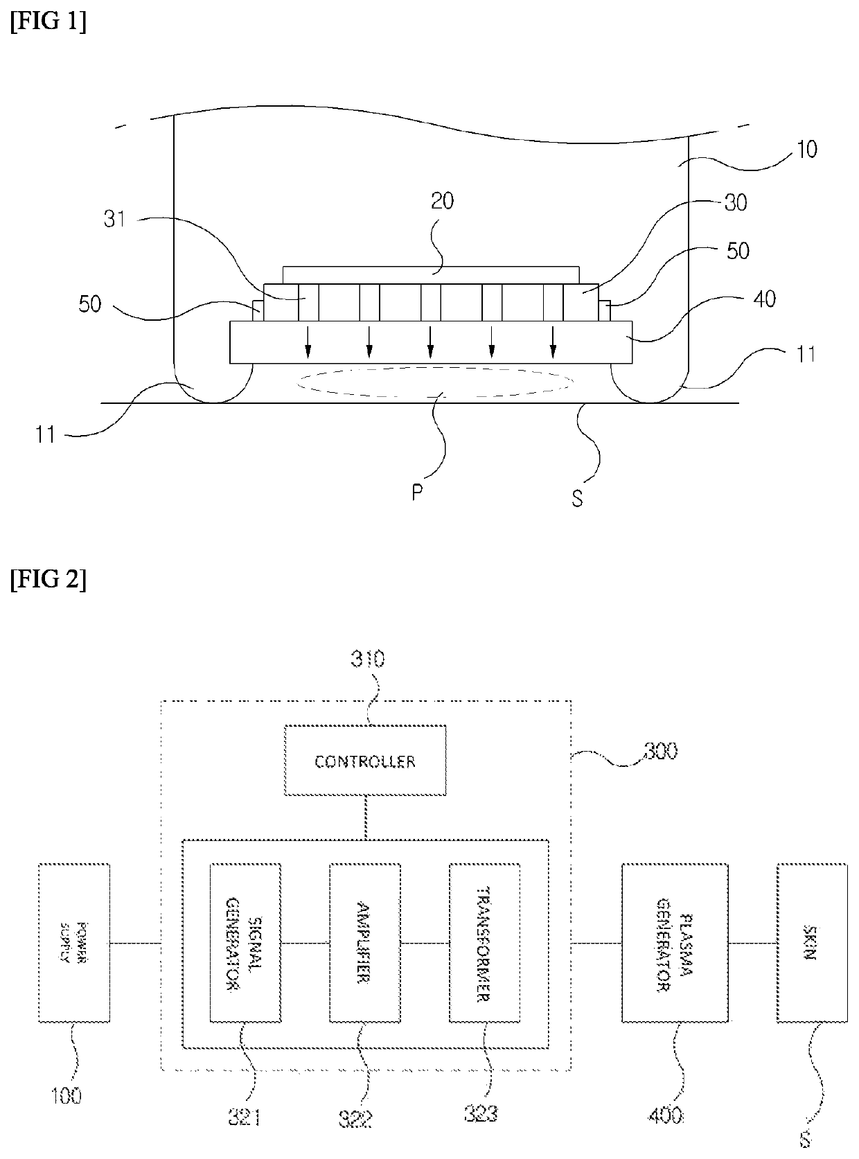
[0034]As illustrated in FIG. 2, a skin treatment apparatus using plasma according to the present invention includes a power supply 100, a high-voltage module 300, and a plasma generator 400. The high-voltage module 300 includes a controller 310, a signal generator 321, an amplifier 322, and a transformer 323.

[0035]The power supply 100 may be an external power source or may be a small-sized portable battery.

[0036]The controller 310 of the high-voltage module 300 controls direct-current (DC) power output from the power supply 100 to be converted into high-frequency and high-voltage alternating-current (AC) power. The signal generator 321 of the high-voltage module 300 generally generates a frequency of 20 kHz or more. The amplifier 322 of the high-voltage module 300 is matched with impedance in a range of 5 to 50 W.

[0037]The transformer 323 of ...


PUM

PropertyMeasurementUnit
pressureaaaaaaaaaa
thicknessaaaaaaaaaa
relative dielectric constantaaaaaaaaaa

Abstract

The present invention relates to a skin treatment apparatus using fractional plasma, in which a plasma generator includes an electrode plate, a dielectric body, a pin holder, a plurality of pins, and a gap maintaining part and further includes a lower support which includes a pin cover, vents, and an auxiliary gap maintaining part. According to the present invention, the plurality of pins are configured as independent electrodes to prevent concentration of plasma, ends of the plurality of pins are pointed to more smoothly generate plasma, the distances between the plurality of pins may be more reliably maintained using the pin cover, plasma generated by the plurality of pins may be evenly emitted onto the skin via the pin cover and vents without being concentrated on a curved region of the skin, and the auxiliary gap maintaining part moves in a vertical direction of the gap maintaining part to adjust a distance between the plurality of pins and the skin.

Description

CROSS REFERENCE TO RELATED APPLICATIONS[0001]This application is a National Phase filing under 35 U.S.C. § 371 of PCT / KR2018 / 001361 filed on Feb. 1, 2018; which application in turn claims priority to Application No. 10-2017-0047276 filed in Korea on Apr. 12, 2017. The entire contents of each application are hereby incorporated by reference.TECHNICAL FIELD[0002]The present invention relates to a skin treatment apparatus using fractional plasma, and more particularly, to a skin treatment apparatus using fractional plasma, in which a dielectric body is provided to generate soft plasma by inducing a dielectric barrier discharge to occur between the skin and a plasma generator, and a plurality of pins are configured as independent electrodes to prevent concentration of plasma.BACKGROUND ART[0003]A state of a material may be divided into a solid state, a liquid state, and a gaseous state. When energy is applied to a gaseous material, electrons are separated from atoms or molecules to caus...

Claims


Application Information

Patent Timeline
Patent Type & Authority Patents(United States)
IPC IPC(8): A61N1/44H05H1/24
CPCA61N1/44H05H1/2406H05H2277/10H05H2240/20H05H2245/34
Inventor KIM, BYOUNG CHOUL
Owner SEOULIN MEDI CARE
Why Eureka
Try Eureka