
Dressing, honing and grinding tool

a technology applied in the field of honing and grinding tools, can solve the problem of limiting the economic efficiency of the processes in which they are currently used, and achieve the effect of improving the economic efficiency of the process

Inactive Publication Date: 2001-06-21
REISHAUER
View PDF0 Cites 8 Cited by
  • Summary
  • Abstract
  • Description
  • Claims
  • Application Information

AI Technical Summary

Problems solved by technology

Since a subsequent machining of the hard abrasive grain studded cutting surfaces is only possible to a limited extent and at great expenditure, such tools are often made by the so-called reversal process, the tool being built up -starting with an exactly made negative mould - from the outside, i.e. the peripheral hard material abrasive grain layer, inwards to the tool-locating bore.
The numerous manufacturing operations and the long bath times for the nickel-embedding of the hard abrasive grains result in long manufacturing times, however, and high manufacturing costs which limit the economic efficiency of the processes in which they are currently used.

Method used


Image

  • Dressing, honing and grinding tool

Examples


Embodiment Construction

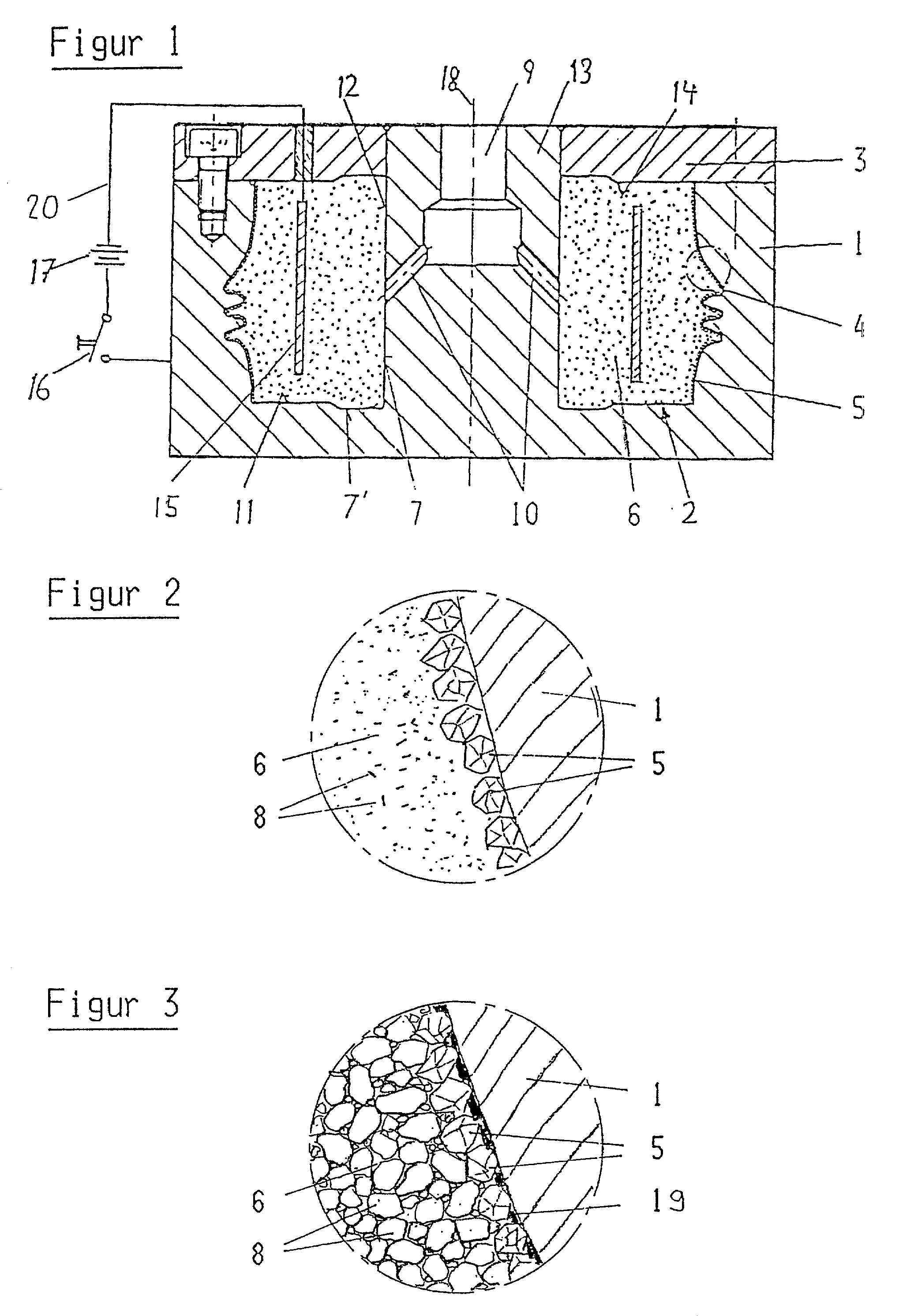
[0010] In the embodiment of the invention selected here, the negative mould 1 for the tool 2 is a pot-shaped metal body produced directly or by the reversal process, which is closed by a lid 3. In cross-section the inner contour of the negative mould 1 corresponds with the peripheral, end face and bore contour trace of the axial section through the tool. The bottom 11 of the hollow space of the negative mould 1, the enveloping surface 12 of the central cylindrical core 13 and the inner face 14 of the lid 3 are provided with an electrically insulating coating. In the closed inside space there are for example one or more annular electrodes 15, which are connected via an insulated conductor to one pole of a direct current source 17, the other pole of which is connected to the negative mould via the switch 16.

[0011] Lying on the peripheral inner surface 4 of the negative mould 1 are the hard material abrasive grains 5. The inside space of the negative mould 1 is filled with a naturally ...


PUM

PropertyMeasurementUnit
sizeaaaaaaaaaa
compositionaaaaaaaaaa
hardaaaaaaaaaa

Abstract

In a negative mould (1) closed by a lid (3), hard material abrasive grains (5) are nickel-attached to the peripheral inside surface. The negative mould (1) contains, in addition to the outside contour (4) of the tool to be manufactured, also the surfaces for the location bore (7) and the end face locations (7') of the said tool. Subsequently the inner space of the negative mould (1) is completely filled with a casting mass (6) interspersed with solid particles (8) and the said mass allowed to harden. The mould (1) is removed by machining or etching. This process permits the inexpensive and economic manufacture of tools coated with hard material abrasive grains.

Description

FIELD AND BACKGROUND OF THE INVENTION[0001] Tools of which the working surfaces are provided with a layer of hard material abrasive grains, such as CBN or diamond, are being used more and more in many manufacturing fields as grinding, honing, cut-off grinding or dressing tools under the designation CBN grinding wheel or grinding worm, CBN honing stone, cut-off grinding disc, form or profile dressing roller, diamond dressing gear etc. Particularly in those applications where they are employed as profile grinding wheel, profile dressing roller or dressing gear, the demands made on the topological accuracy of their cutting (abrading) surface are high. Since a subsequent machining of the hard abrasive grain studded cutting surfaces is only possible to a limited extent and at great expenditure, such tools are often made by the so-called reversal process, the tool being built up -starting with an exactly made negative mould - from the outside, i.e. the peripheral hard material abrasive gr...

Claims


Application Information

Patent Timeline
Patent Type & Authority Applications(United States)
IPC IPC(8): B24B33/08B24B53/12B24D3/00B24D3/02B24D3/06B24D3/14B24D3/28B24D5/02B24D18/00
CPCB24B33/08B24D3/06B24D5/02B24D18/009
Inventor GERL, ROLF
Owner REISHAUER
Learn More