Electromagnet and magnetic field generating apparatus

a technology of generating apparatus and magnetic field, which is applied in the direction of magnetic bodies, separation processes, applications, etc., can solve the problems of high manufacturing cost, increased leakage of magnetic field from magnetic poles, and complicated structure of magnetic poles

Inactive Publication Date: 2001-07-26
HITACHI LTD +1
View PDF0 Cites 64 Cited by
  • Summary
  • Abstract
  • Description
  • Claims
  • Application Information

AI Technical Summary

Problems solved by technology

However, in a case when a magnetic field strength increases, due to an affect of a magnetic saturation of an iron core which is used in a magnetic pole of the electromagnet, a leakage magnetic field from the magnetic pole increases.
As a result, in a case where there is a chance of a use of the beam with a wide energy range, since the maximum magnetic field strength of the electromagnet is limited by the above stated reasons, it is necessary to employ a bending electromagnet having a large radius of curvature.
However, since it is necessary to provide the projection to the magnetic pole, a magnetic pole structure becomes a complicated one.
In company with this, also a manufacturing cost becomes high.
Further, in the above stated second prior art, similarly to the first prior art, since it is necessary to provide the projection to the pole piece, the pole piece structure becomes a complicated one.
In company with those requirements, also a manufacturing cost becomes high.

Method used


Image

  • Electromagnet and magnetic field generating apparatus
  • Electromagnet and magnetic field generating apparatus
  • Electromagnet and magnetic field generating apparatus

Examples


first embodiment

[0036] First Embodiment

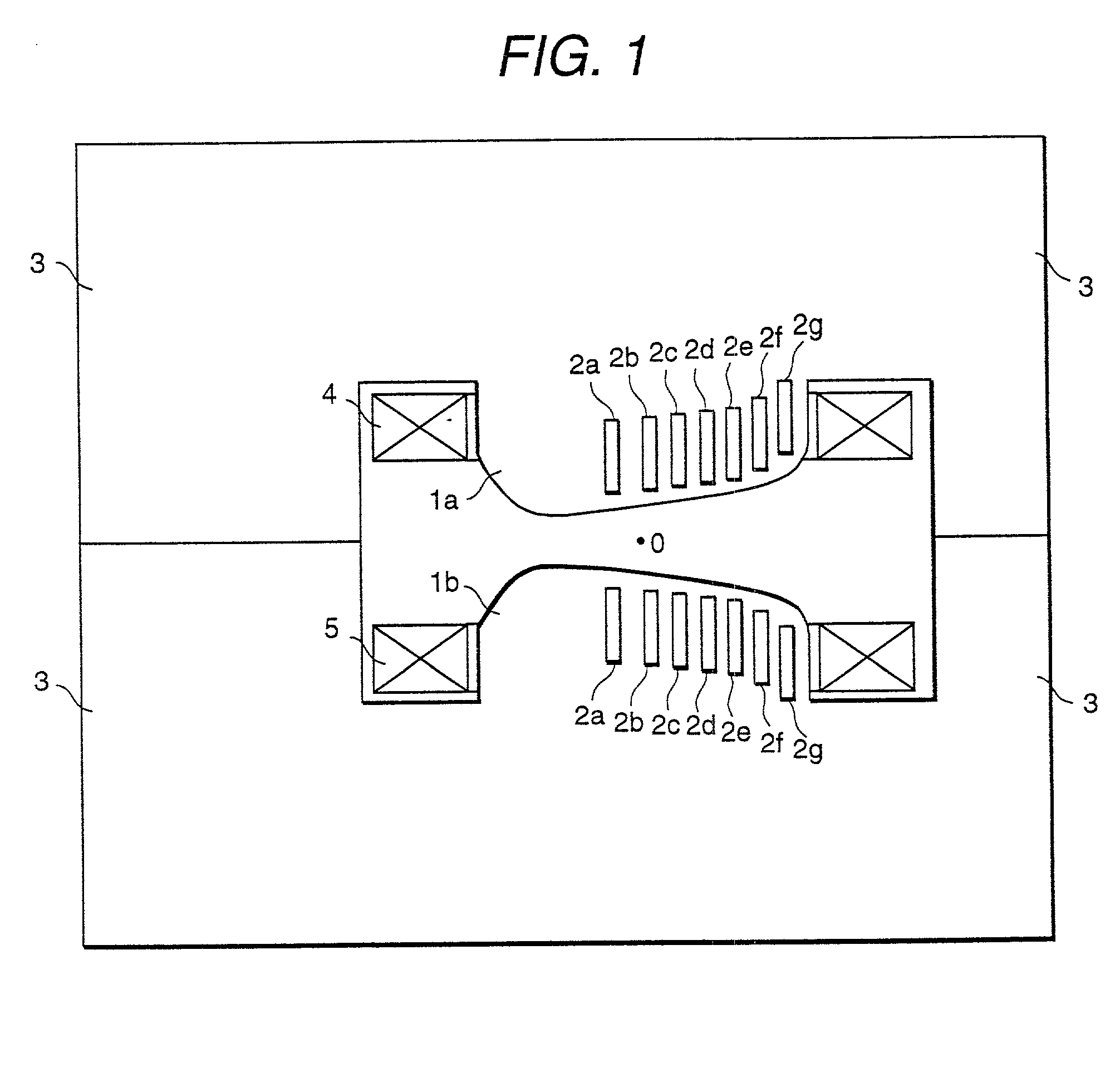
[0037] Hereinafter, a first embodiment of an electromagnet according to the present invention will be explained referring to FIG. 1. FIG. 1 is a longitudinal cross-sectional view showing a combined function bending magnet to which the present invention is applied. This electromagnet has both functions about a bending electromagnet (a two-pole electromagnet) and a quandrupole electromagnet and it is assumed that the electromagnet is provided on an orbit of an orbital fighting beam.

[0038] This electromagnet is constituted by a pair of magnetic pole 1a and magnetic pole 1b which are arranged oppositely by sandwiching the orbit of the beam, a return yoke 3 for forming a magnetic path by connecting the magnetic pole 1a and the magnetic pole 1b, and exciting coils 4 and 5, etc.

[0039] In an interior portion of each of the magnetic pole 1a and the magnetic pole 1b, plural spaces 2a-2g are provided by putting side by side toward a horizontal direction (a lateral direct...

second embodiment

[0062] Second Embodiment

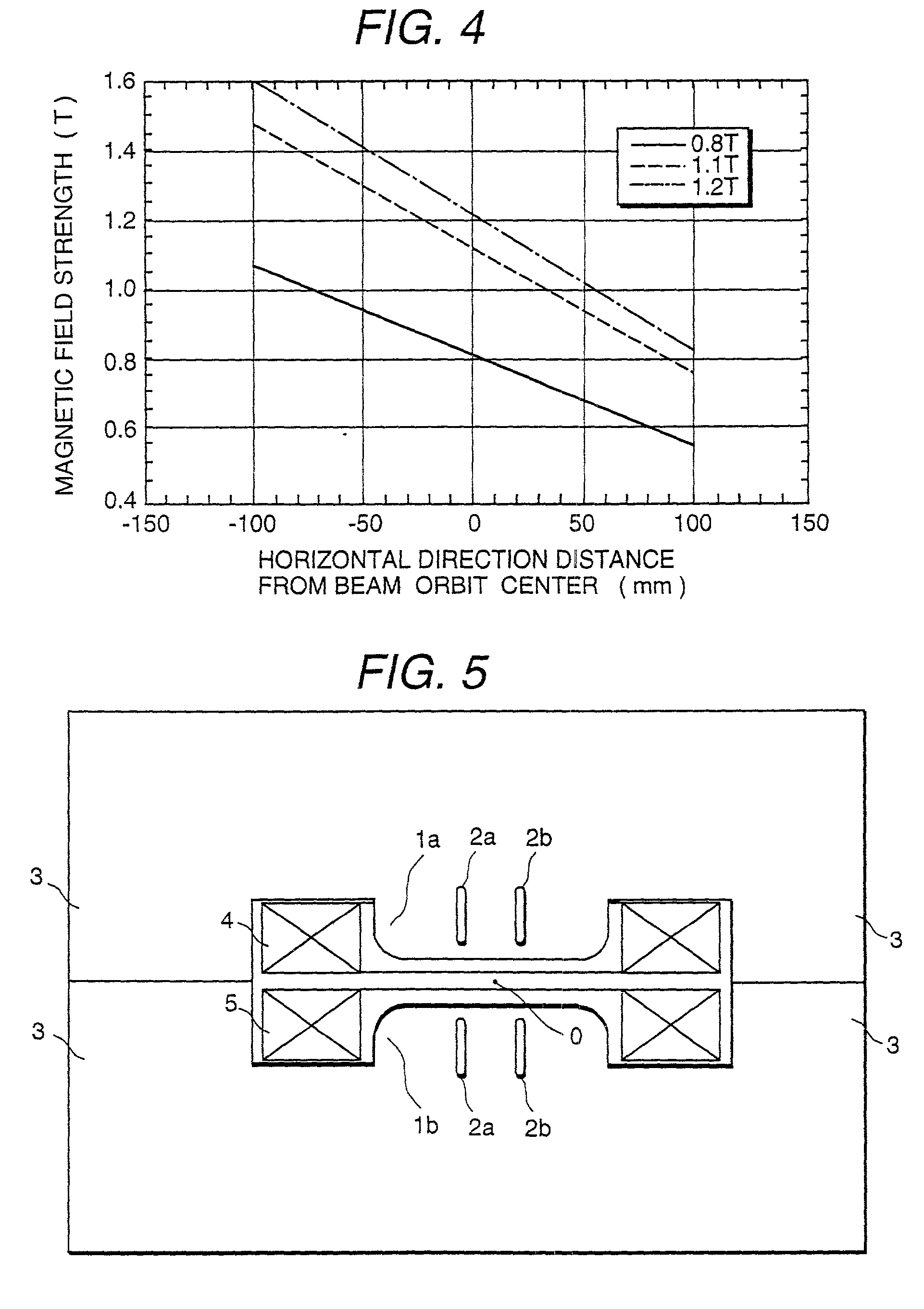
[0063] Next, a second embodiment of an electromagnet according to the present invention will be explained referring to FIG. 5. FIG. 5 is a longitudinal cross-sectional view showing a deflective electromagnet in which the present invention is applied. This electromagnet is assumed that the electromagnet is provided on an orbit of a circulating charged particle beam.

[0064] This electromagnet is comprised of a pair of magnetic pole 1a and magnetic pole 1b which are arranged oppositely by sandwiching the orbit of the charged particle beam, a return yoke 3 for forming a magnetic path by connecting the magnetic pole 1a and the magnetic pole 1b, and exciting coils 4 and 5, etc. In an interior portion of each of the magnetic pole 1a and the magnetic pole 1b, two spaces 2a and 2b are provided at an area near a surface of the magnetic pole by putting side and side toward a horizontal direction (a lateral direction in FIG. 5). A horizontal direction position of the resp...

third embodiment

[0079] Third Embodiment

[0080] Next, a third embodiment according to the present invention will be explained referring to FIG. 8. FIG. 8 is a longitudinal cross-sectional view showing a quandrupole magnet in which the present invention is applied. This electromagnet is assumed that the electromagnet is provided on an orbit of a circulating charged particle beam.

[0081] The electromagnet is comprised of two pairs of magnetic pole 1a and magnetic pole 1b which are arranged to be a point symmetry against a center O of the beam orbit of the charged particle beam, a return yoke 3 which forms a magnetic path by connecting adjacent magnetic poles each other, and exciting coils 4 and 5, etc. In an interior portion of the magnetic pole 1a and the magnetic pole 1b, respective two spaces 2a and 2b are provided at a surrounding portion of the central portion of the magnetic pole at an area near to a surface of the magnetic pole.

[0082] The return yoke 3 is divided into an upper portion and a lower...


PUM

PropertyMeasurementUnit
magnetic fieldaaaaaaaaaa

Abstract

An electromagnet comprises a pair of magnetic pole 1a and 1b, a return yoke 3, exciting coils 4 and 5, etc. In an interior portion of a magnetic pole, plural spacers 2a-2g are provided putting side by side in a horizontal direction. Each of the spaces 2a-2g is an air layer and a longitudinal cross-section is a substantially rectangular shape and the space has a lengthily extending slit shape in a vertical direction against a paper face in FIG. 1. The plural spaces are mainly arranged toward a right side from a beam orbit center O and an interval formed between adjacent spaces is narrower toward the right side. The electromagnet having a simple magnetic pole structure and a wide effective magnetic field area in a case where a maximum magnetic field strength is increased can be secured.

Description

[0001] 1. Technical Field[0002] The present invention relates to an electromagnet for bending an orbit of a charged particle beam and a magnetic field generating apparatus for generating a magnetic field in an air gap and, in particularly to an electromagnet suitable for use in a physical experimentation use accelerator, an industrial use accelerator and a medical treatment use accelerator or a magnetic field generating apparatus for use in a medical treatment use diagnosing instrument such as MRI (Magnetic Resonance Imager).[0003] 2. Prior Arts[0004] In generally, an electromagnet used in an accelerator is designed to have a desirable magnetic field distribution in a predetermined area which is determined by a size of a charged particle beam (hereinafter, it is called as a beam). However, in a case when a magnetic field strength increases, due to an affect of a magnetic saturation of an iron core which is used in a magnetic pole of the electromagnet, a leakage magnetic field from t...

Claims


Application Information

Patent Timeline
Patent Type & Authority Applications(United States)
IPC IPC(8): A61B5/055H01F7/02H01F7/20H05H13/04H01J37/147H05H7/04
CPCH01F7/20H01J37/1472H01J2237/152H05H7/04
Inventor TADOKORO, MASAHIROHIROTA, JUNICHIHIRAMOTO, KAZUOUMEZAWA, MASUMIIWASHITA, YOSHIHISA
Owner HITACHI LTD
Why Eureka
Try Eureka