

Magnetically driven axial-flow pump
- Summary
- Abstract
- Description
- Claims
- Application Information
AI Technical Summary
Benefits of technology
Problems solved by technology
Method used
Image

Examples
Embodiment Construction
[0017] Referring to the drawings, an embodiment of magnetically driven axial--flow pump of the present invention will now be described.
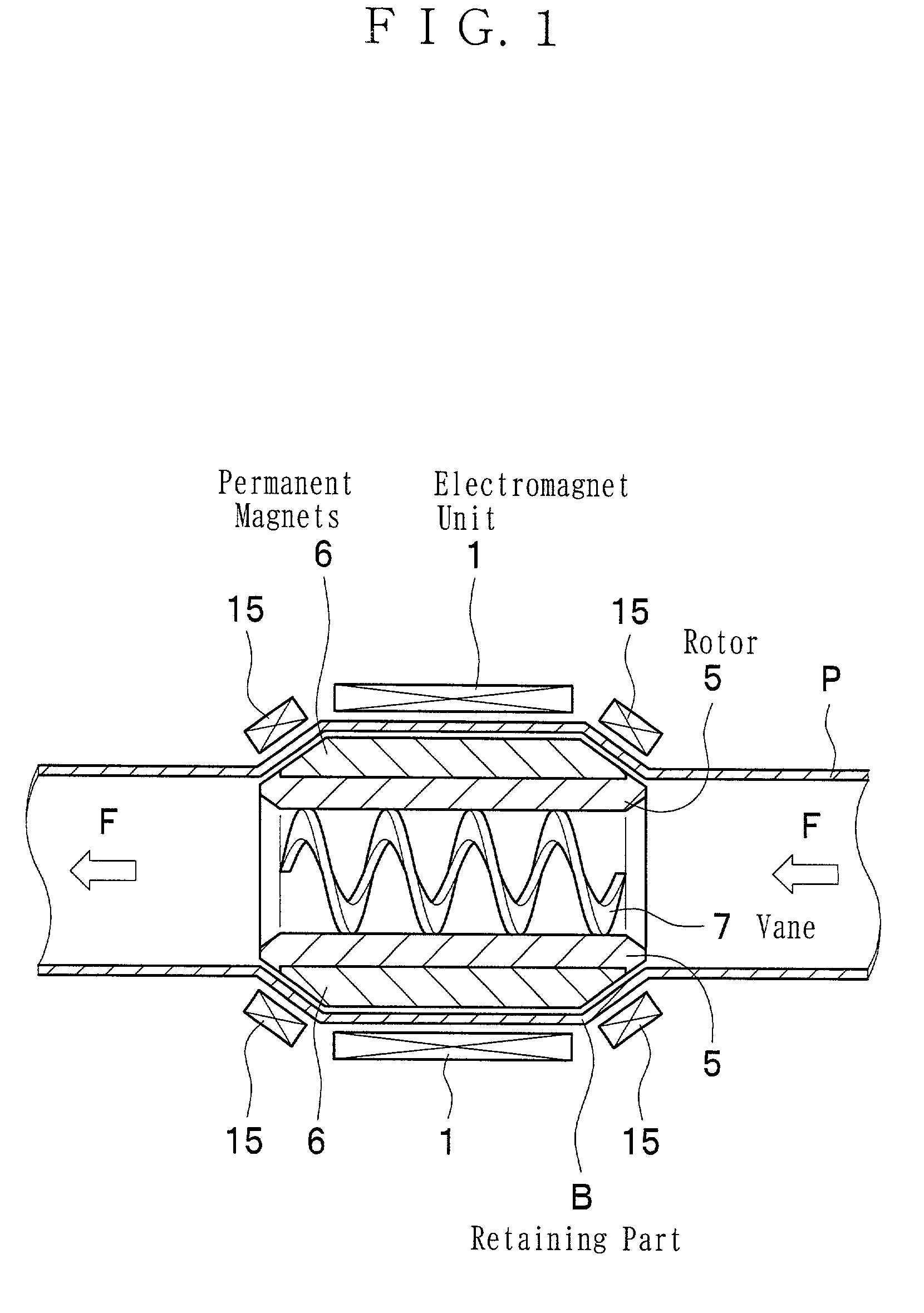
[0018] In FIG. 1, blood flows in a pipe "P". The pipe "P" has a retaining part "B" which is expanded in diameter and holds the magnetically driven axial-flow pump.
[0019] The magnetically driven axial-flow pump consists basically of an electromagnet unit 1, a rotor 5, permanent magnets 6, and a vane 7.
[0020] The rotor 5 is disposed in the retaining part "B" so as to be freely rotatable. The rotor 5 is made of a grindable material such as iron or ceramic. The rotor 5 made of iron or ceramic is hard, strong, and durable.
[0021] The rotor 5 is in the shape of a cylinder and its wall tapers off at each end so as to make its inner diameter enlarge toward said end.
[0022] The spiral vane 7 is formed on the inner surface of the rotor 5. The central portion along the axis of the vane 7 is hollow. Therefore, the rotor 5 and the vane 7 can be made in one piece wi...
PUM
 Abstract
Description
Claims
Application Information