Automotive air conditioning system

a technology for air conditioning systems and automobiles, applied in the direction of refrigeration components, machines/engines, process and machine control, etc., can solve the problems of ineffective cooling performance of the cooling section of the air conditioning system, failure of the automotive air conditioning system to quickly carry out the shifting from the low-power mode to the high-power mode,

Inactive Publication Date: 2001-08-23
CALSONIC KANSEI CORP
View PDF0 Cites 48 Cited by
  • Summary
  • Abstract
  • Description
  • Claims
  • Application Information

AI Technical Summary

Problems solved by technology

However, due to its inherent construction, the above-mentioned known automotive air conditioning system has failed to quickly carry out the shifting from the low-power mode to the h

Method used


Image

  • Automotive air conditioning system
  • Automotive air conditioning system
  • Automotive air conditioning system

Examples


Embodiment Construction

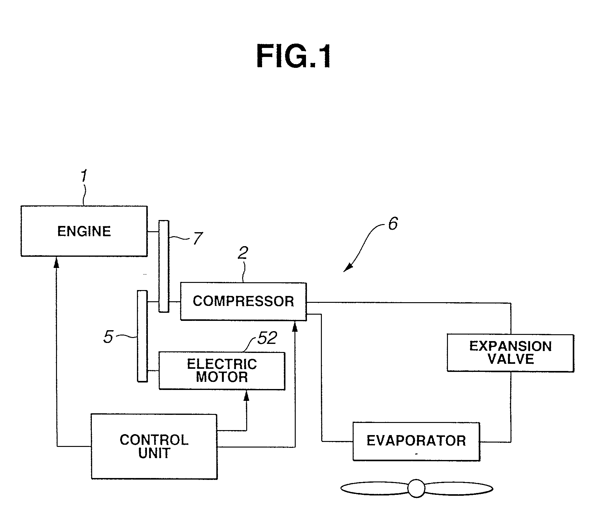
[0024] Referring to FIG. 1 of the drawings, there is shown the outline of the present invention, which depicts the relation between various elements practically used in the invention.

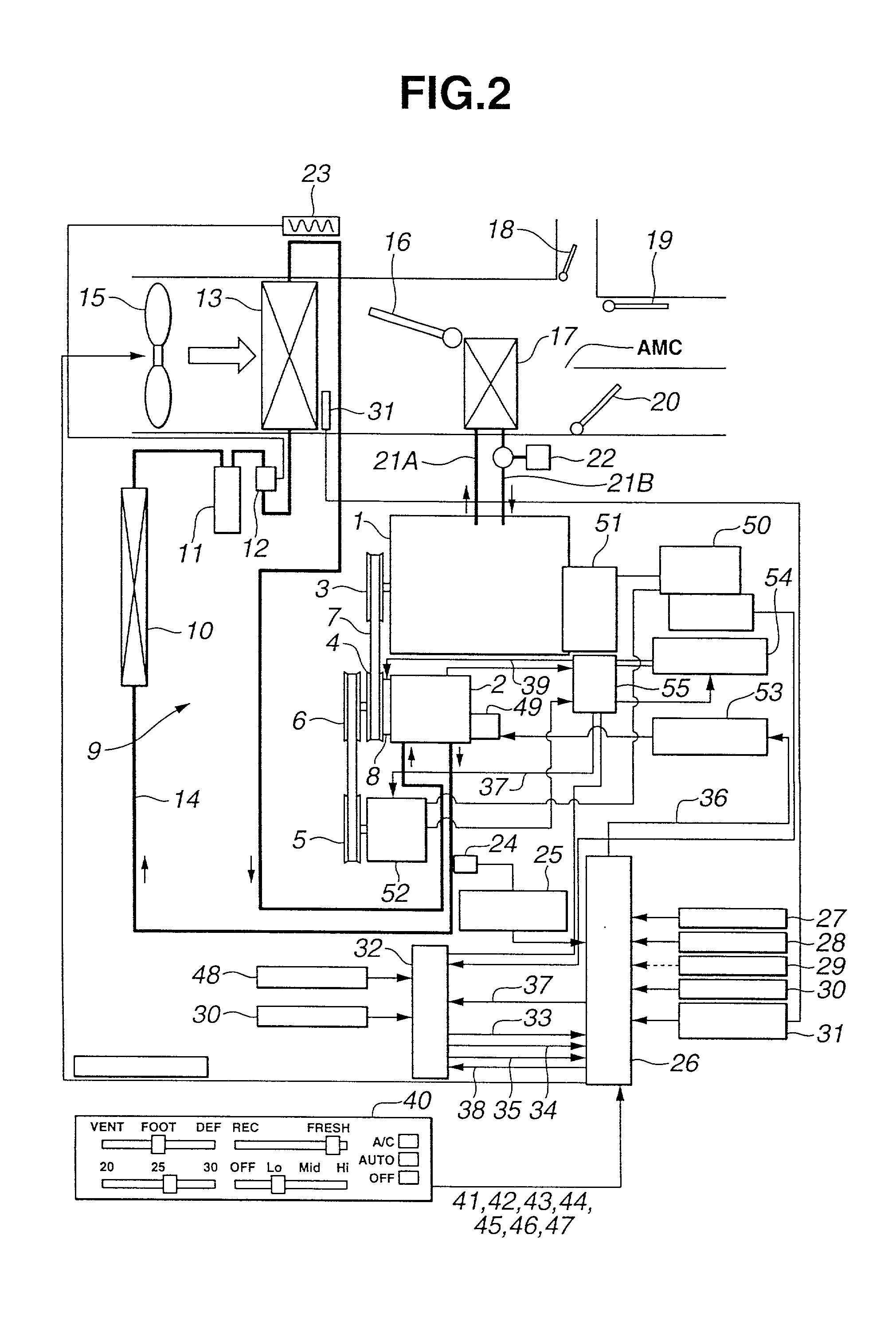
[0025] Referring to FIG. 2, there is shown a block diagram of an automotive air conditioning system of the present invention. As will become apparent as the description proceeds, the compressor used in this embodiment of a hybrid type.

[0026] In FIG. 2, denoted by numeral 1 is an internal combustion engine of a motor vehicle. The engine 1 is has a first drive pulley 3 driven by an output shaft of the engine 1. Denoted by numeral 2 is a compressor of a cooling section 9 of the air conditioning system 100A, whose input shaft has a first driven pulley 4 connected thereto through an electric clutch 8. The first drive pulley 3 and the first driven pulley 4 are connected through a V-belt 7 to permit transmission of power of the engine 1 to the input shaft of the compressor 2. A second driven pulley 6 is connec...


PUM


Abstract

An air conditioning system for use in a motor vehicle powered by an internal combustion engine is described. The system comprises an electric motor powered by a battery; a compressor arranged to be powered by at least one of the internal combustion engine and the electric motor; and a control unit that controls the driving of the compressor. The control unit is configured to execute driving the compressor by only the electric motor when the combustion engine is under an idling stop; restarting the combustion engine upon expiration of a first given time from the time when the idling stop has occurred, so that thereafter the compressor is driven by both the combustion engine and the electric motor; and stopping the driving of the compressor by the electric motor upon expiration of a second given time from the restarting of the combustion engine, so that thereafter the compressor is driven by only the combustion engine.

Description

[0001] 1. Field of the Invention[0002] The present invention relates in general to automotive air conditioning systems and more particularly to automotive air conditioning systems of a type suitable for motor vehicles which exhibit an excellent fuel consumption, such as a motor vehicle which is constructed to stop its engine when stops due to a red light at a crossing or the like or a hybrid motor vehicle which is equipped with both an internal combustion engine and an electric motor and effectively powered by at least one of them. More specifically, the present invention relates to an air conditioning systems for such low fuel consumption motor vehicles, which is kept operative even when the motor vehicle is under an idling step stopping the engine.[0003] 2. Description of the Prior Art[0004] In order to clarify the task of the present invention, a known automotive air conditioning system of the above-mentioned type will be described, which is disclosed in Japanese Laid-open Patent...

Claims


Application Information

Patent Timeline
IPC IPC(8): B60H1/32F25B49/02
CPCB60H1/3208F25B49/025B60L1/003B60L1/02B60L15/2045B60L50/10B60L2240/34B60L2240/662B60L2240/80B60L2250/26B60L2260/26Y02T10/64Y02T10/7072Y02T10/72Y02T90/16Y02T10/70
Inventor HARA, JUNICHIRO
Owner CALSONIC KANSEI CORP
Why Eureka
Try Eureka