Heat storage air conditioning apparatus and heat storage estimating method
a technology of heat storage air conditioning and heat storage, which is applied in the direction of storage heaters, heating types, furnace-tube steam boilers, etc., can solve the problem of inability to appropriately set the discharging pattern
- Summary
- Abstract
- Description
- Claims
- Application Information
AI Technical Summary
Problems solved by technology
Method used
Image

Examples
first embodiment
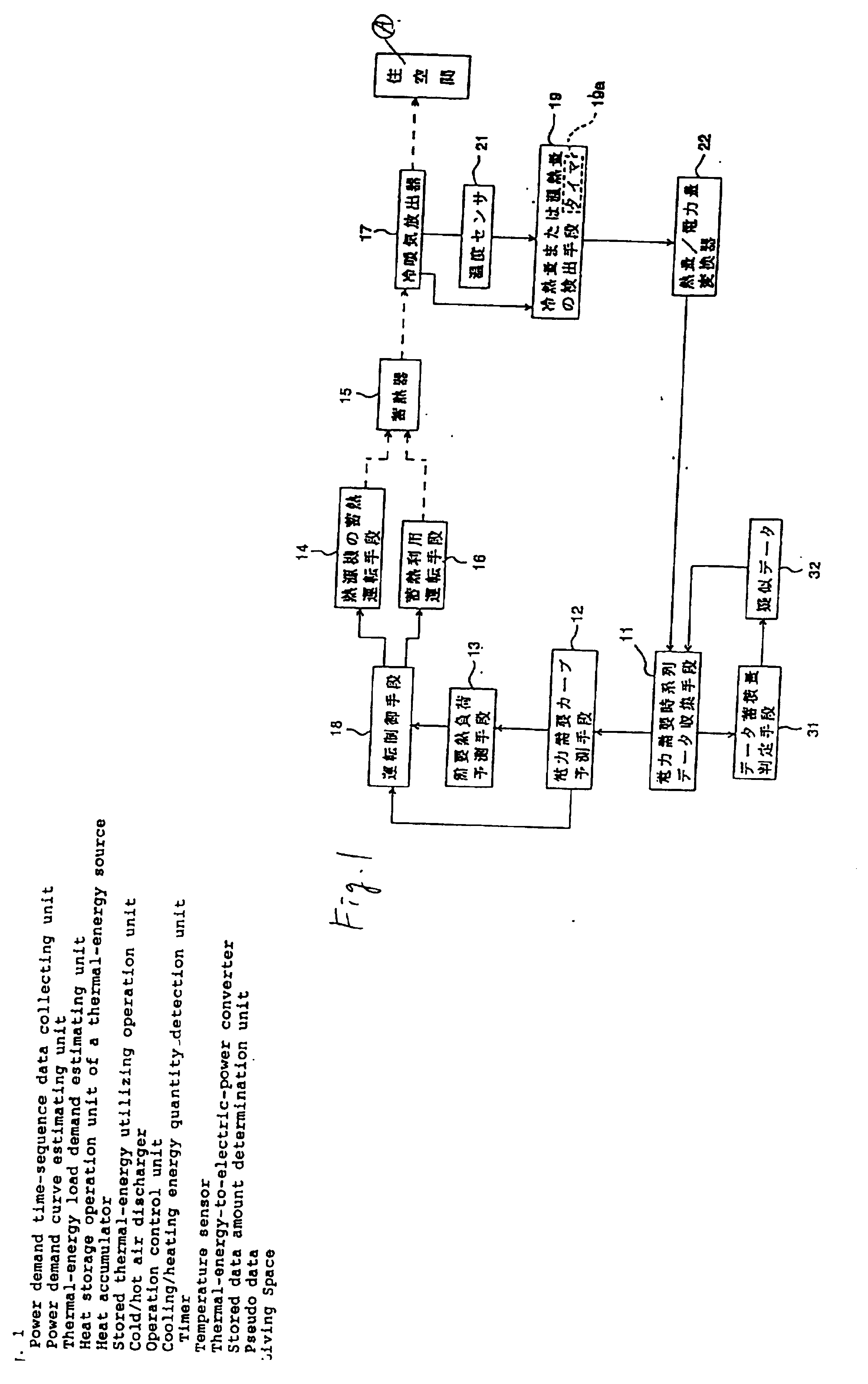
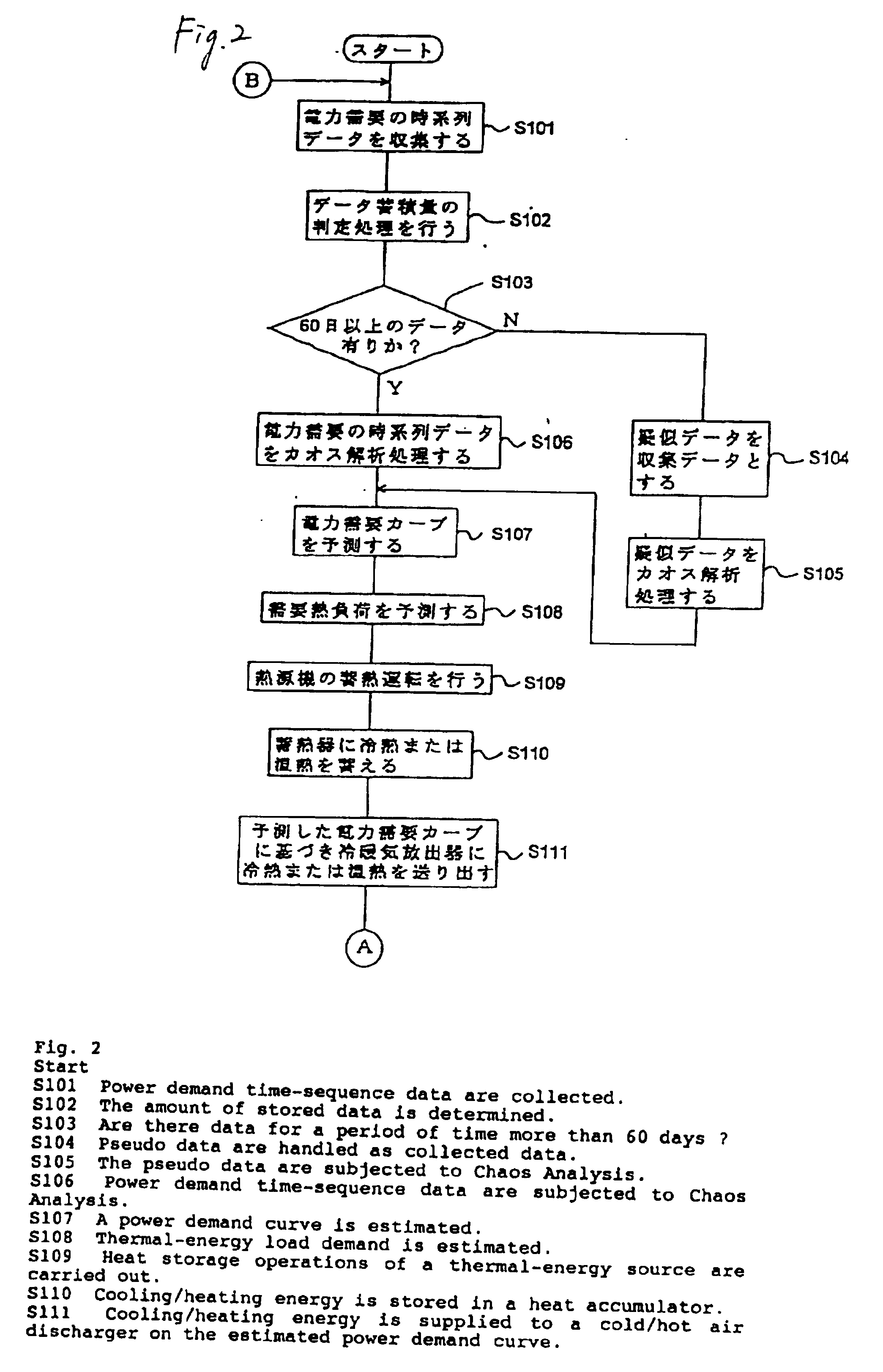
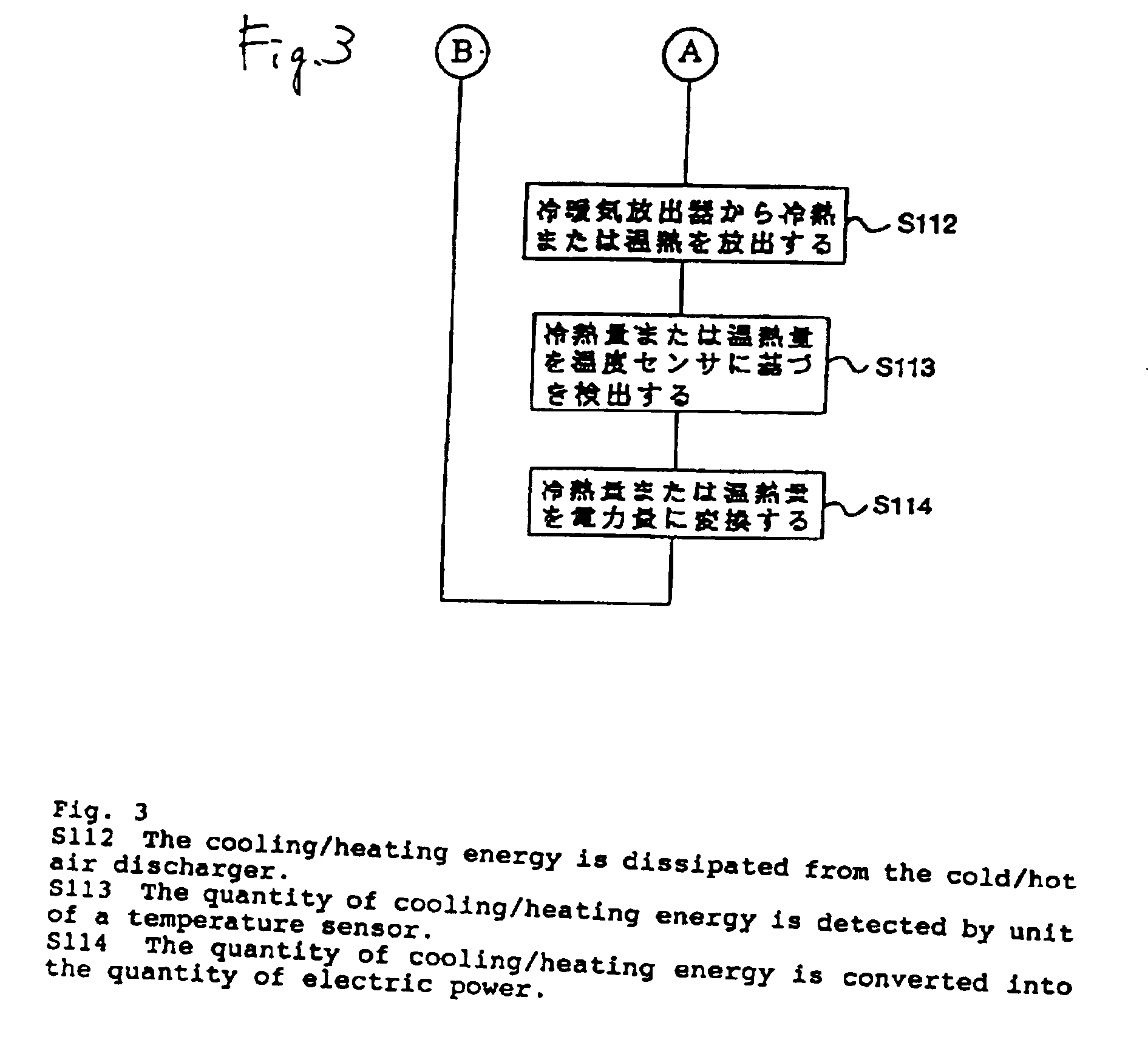
[0095] FIG. 1 is a basic block diagram of a heat storage air conditioner according to the present invention. FIGS. 2 and 3 are flowcharts for use in describing processing operations of the heat storage air conditioner. FIG. 4 is a diagram for explaining a method of estimating a power demand curve for the next day using pseudo data of the heat storage air conditioner. FIG. 5 is a table that shows an example of numerical values regarding the quantity of power electricity represented by the pseudo data. FIG. 6 is an example of repetitive heat quantity pattern used in the heat storage air conditioner of the first embodiment.
[0096] In FIG. 1, reference numeral 11 designates a power demand time-sequence data collecting unit for collecting power demand time-sequence data. Reference numeral 31 designates stored data amount determination unit that determines the amount of data stored by the power demand time-sequence data collecting unit 11. If a predetermined amount of stored data (e.g., 60...
second embodiment
[0112] FIG. 7 is a basic block diagram of a heat storage air conditioner according to the present invention. FIGS. 8 and 9 are flowcharts for use in describing processing operations of the heat storage air conditioner. The elements shown in FIG. 7 that are the same as those of the previously-described first embodiment shown in FIG. 1 are assigned the same reference numerals.
[0113] In FIG. 7, reference numeral 11 designates a power demand time-sequence data collecting unit for collecting power demand time-sequence data. Reference numeral 31 designates stored data amount determination unit that determines the amount of data stored by the power demand time-sequence data collecting unit 11. If a predetermined amount of stored data (e.g., 60 days+ worth of data) has not been achieved yet, the stored data amount determination unit sends pseudo data 32 to the power demand time-sequence data collecting unit 11. As in the first embodiment, the following descriptions will be based on an examp...
third embodiment
[0122] FIG. 10 is a basic block diagram of a heat storage air conditioner according to the present invention. FIGS. 11 and 12 are flowcharts for use in describing processing operations of the heat storage air conditioner. FIG. 13 is a diagram for use in describing a method of estimating a power demand curve for the next day using pseudo data of the heat storage air conditioner. FIG. 14 is a table that shows an example of numerical values regarding the quantity of power electricity represented by the pseudo data used in the heat storage air conditioner of the third embodiment. FIG. 15 is, a diagram showing a composite heat quantity pattern that is used in the heat storage air conditioner of the present invention and consists of the quantity of thermal energy defined by dissipating operation pattern A of a heat accumulator and the quantity of thermal energy defined by patterns B1 and B2 obtained at the time of air-conditioning operations of a heat source. FIG. 16 is a diagram showing ...
PUM
 Abstract
Description
Claims
Application Information
 - R&D
- Intellectual Property
- Life Sciences
- Materials
- Tech Scout
- Unparalleled Data Quality
- Higher Quality Content
- 60% Fewer Hallucinations
Browse by: Latest US Patents, China's latest patents, Technical Efficacy Thesaurus, Application Domain, Technology Topic, Popular Technical Reports.
© 2025 PatSnap. All rights reserved.Legal|Privacy policy|Modern Slavery Act Transparency Statement|Sitemap|About US| Contact US: help@patsnap.com