This helps you quickly interpret patents by identifying the three key elements:
Problems solved by technology
Method used
Benefits of technology
0019] The present invention aims to simplify the technique of laparoscopy-assisted vaginal hysterectomy by ensuring good visibility of the organs and a reliable anatomical identification.
0020] The present invention aims also to provide a manipulator which would make it possible to make an incision in and cut
Problems solved by technology
Whether during a simple check-up or a surgical operation on the uterus, a surgeon is confronted with a certain number of problems: inherent limited visibility, anatomical identification, manipulation of the organs.
In the particular case of a surgical operation, an additional difficulty arises from the fact that the incision must be precise and must avoid damaging the surrounding tissues.
Nevertheless, the manipulators curren
Method used
Image
Click on the blue label to locate the original text in one second.
Reading with bidirectional positioning of images and text.
Examples
first embodiment
[0085] The up position B or down position A is controlled by control means and is made safe by safety means, as in the manipulator according to the However, these means take a different form in this case.
[0086] As in the manipulator according to the first embodiment, the manipulator also comprises control means which control the rotating movement of the electrode 4. In this case also, these control means are able to perform a rotating movement which may be transmitted to the belt 5 supporting the electrode 4 via transmission means. However, these means take a different form in this case.
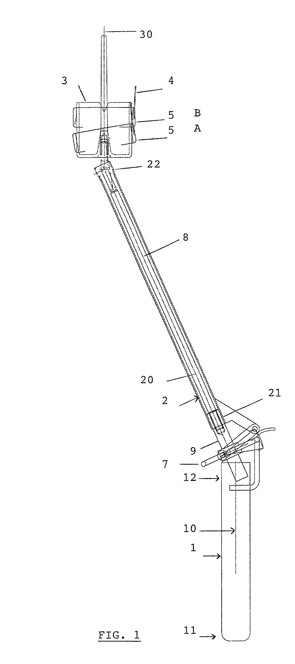
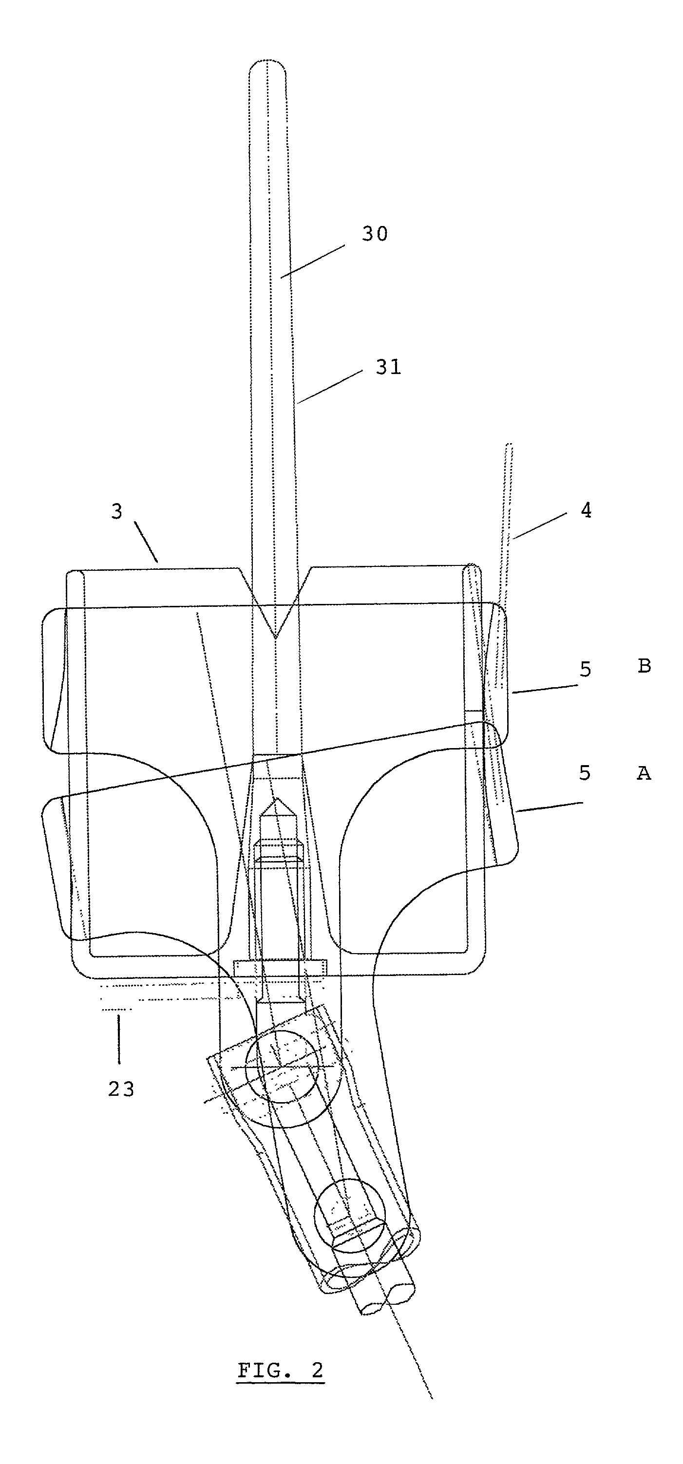
[0087] More precisely, the handle 1 of this manipulator, which is ergonomically shaped, is provided in its proximal part 12 with an end piece 41, as shown in FIG. 7. This end piece 41 has a longitudinal axis 40 which merges with the longitudinal axis 20 of the arm 2. Furthermore, the inside of the end piece 41 comprises a groove 46, the function of which will be described later.
second embodiment
[0088] The manipulator according to this second embodiment further comprises a ring or barrel 42 with a distal part 43 and a proximal part 44, as illustrated in FIG. 8. In order to use the manipulator, this ring or barrel 42 must be fixed, firstly, via its distal part 43 to the distal part 21 of the arm 2 and, secondly, via its proximal part 44 to the end piece 41 of the handle 1, as illustrated in FIGS. 8, 9a and 9b.
[0089] Once fixed to the arm 2 and to the end piece 41, the ring or barrel 42 constitutes in this embodiment the control means via which is controlled the rotating movement of the sectioning device, that is to say the belt 5 and the electrode 4. Specifically, the ring or barrel 42 is able to perform a rotating movement about the longitudinal axis 20 of the arm 2. This rotating movement may be transmitted to the belt 5 via a shaft 8 located inside the arm 2, as in the first embodiment. The shaft 8 thus acts as a transmission means.
[0090] Nevertheless, as in the first emb...
PUM
Abstract
The present invention relates to a uterine manipulator comprising at least (i) a handle (1) which has a longitudinal axis (10), (ii) an arm (2) which also has a longitudinal axis (20) with a distal end (21) connecting it to the handle (1) and a proximal end (22), and (iii) a head (3) which has a longitudinal axis (30) and which is attached to the proximal end (22) of the arm (2), the shape and length of said arm (2) being sufficient to allow the head (3) of said arm to be introduced into the vaginal cavity, characterized in that said head (3) is provided with a sectioning device (4) arranged on a support (5), allowing the vaginal wall to be sectioned, this sectioning device (4) being arranged at a certain distance from the longitudinal axis (30) of the head (3) and being able to perform a rotating movement, preferably of 360 degrees, about said longitudinal axis (30).
Description
SUBJECT OF THE INVENTION[0001] The present invention relates to a uterine manipulator for use in laparoscopy-assisted vaginal hysterectomy or in total laparoscopic hysterectomy.STATE OF THE ART[0002] The function of uterine manipulators is essentially to help surgeons to visualize the peritoneal cavity and the uterus by laparoscopy, during a check-up or diagnostic examination or during a surgical operation, in particular during a hysterectomy.[0003] Various types of uterine manipulators are known, which consist essentially of an arm fitted with a head for introduction into the uterus via the vagina.[0004] Whether during a simple check-up or a surgical operation on the uterus, a surgeon is confronted with a certain number of problems: inherent limited visibility, anatomical identification, manipulation of the organs.[0005] In the particular case of a surgical operation, an additional difficulty arises from the fact that the incision must be precise and must avoid damaging the surroun...
Claims
Application Information
Patent Timeline
Application Date:The date an application was filed.
Publication Date:The date a patent or application was officially published.
First Publication Date:The earliest publication date of a patent with the same application number.
Issue Date:Publication date of the patent grant document.
PCT Entry Date:The Entry date of PCT National Phase.
Estimated Expiry Date:The statutory expiry date of a patent right according to the Patent Law, and it is the longest term of protection that the patent right can achieve without the termination of the patent right due to other reasons(Term extension factor has been taken into account ).
Invalid Date:Actual expiry date is based on effective date or publication date of legal transaction data of invalid patent.