Bone implant and method of securing

a bone implant and bone cement technology, applied in the field of implants and methods of securing implants to bone, can solve the problems of cracking of bone cement slabs, deformation of bone cement, and cracks often initiating at the site of defects

Inactive Publication Date: 2001-09-20
BONUTTI SKELETAL INNOVATIONS
View PDF0 Cites 77 Cited by
  • Summary
  • Abstract
  • Description
  • Claims
  • Application Information

AI Technical Summary

Benefits of technology

[0010] The bone engagement portion of the implant is preferably in abutting engagement with the bone so that there is not a continuous layer of cement between the implant and the bone across the full extent of the interface between the implant and the bone. This discontinuity in the layer of bone cement inhibits crack propagation.

Problems solved by technology

There may be defects in the cement such as an air bubble, an impurity or unreacted PMMA powder.
It is known for slabs of bone cement to crack.
With bone cement as with many materials a crack often initiates at the site of a defect.
Or, a slab of bone cement could fail and crack from other causes such as stress or trauma.
If bone cement is present in a continuous mass such as a slab, a crack propagates through the slab, resulting in complete failure of the cement system.
For an aligned compartment system to fail in shear the cement plugs must fail in shear which requires substantially more stress than that needed to cause failure of a slab.

Method used


Image

  • Bone implant and method of securing
  • Bone implant and method of securing
  • Bone implant and method of securing

Examples


Embodiment Construction

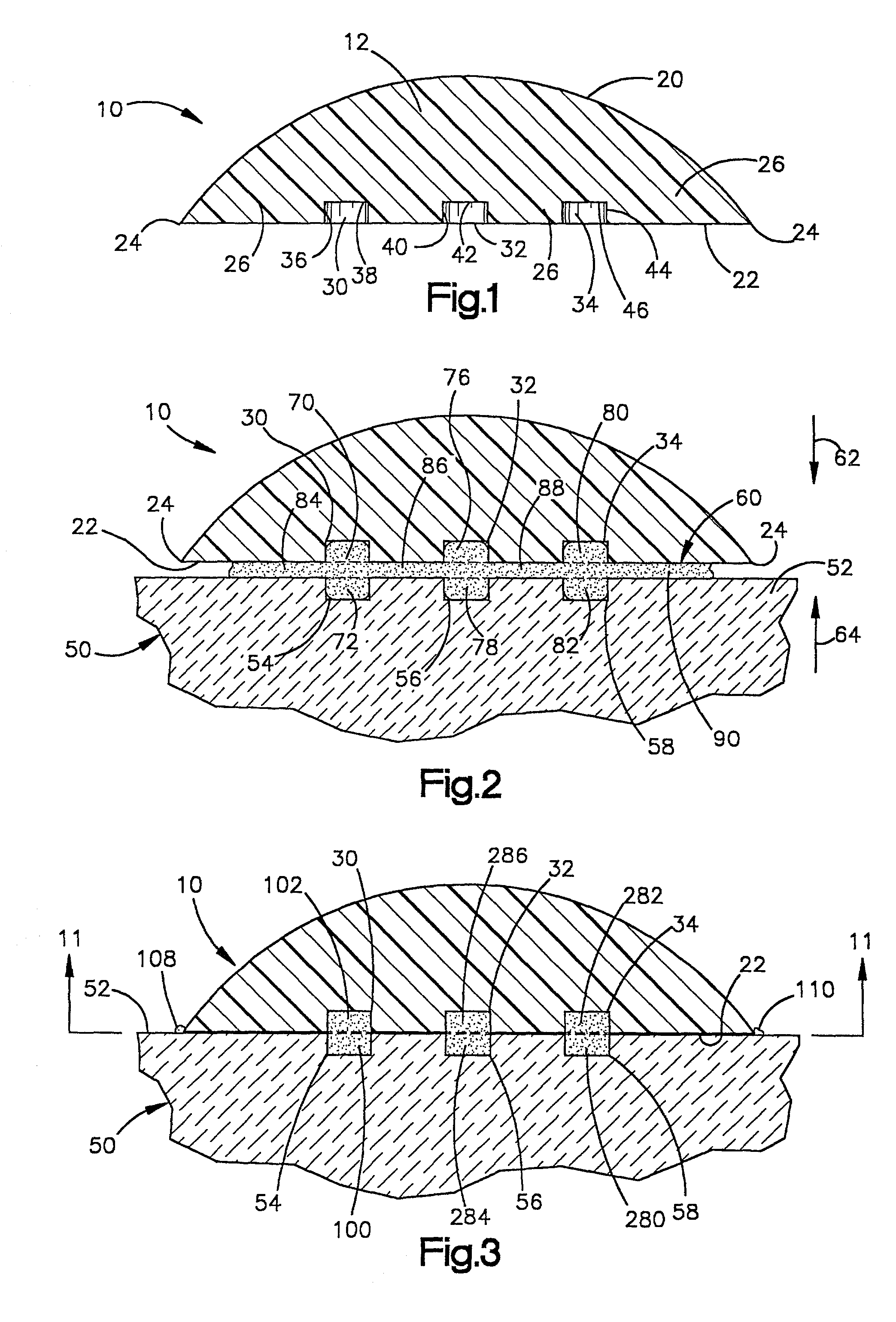
[0030] The present invention relates to an implant and to a method of securing an implant to a bone with bone cement. The present invention is applicable to various implant constructions. As representative of the present invention, FIG. 1 illustrates a patellar implant 10. The implant 10 is made of a body of material 12. The material 12 is preferably a biocompatible plastic material. A preferred material is ultra high molecular weight polyethylene (UHMWPE). Alternatively, the implant 10 can be a metal backed plastic component having a bone engagement portion made of metal and an articulating surface made of plastic.

[0031] The implant 10 has an arcuate articulating surface 20 and a planar bone engagement surface 22. The surfaces 20 and 22 intersect at the outer periphery 24 of the implant 10.

[0032] A bone engagement portion 26 of the implant 10 includes the portion of the implant 10 adjacent to or close to the bone engagement surface 22. The bone engagement portion 26 includes surfac...


PUM

PropertyMeasurementUnit
diametersaaaaaaaaaa
diametersaaaaaaaaaa
diametersaaaaaaaaaa

Abstract

The present invention is an implant for securing to a bone to form a plurality of cement cells. The implant has a bone engagement portion for engagement with the bone. The implant has surfaces defining a first plurality of cement compartments in the bone engagement portion for alignment with a second plurality of cement compartments in the bone to form a plurality of cement cells extending between the implant and the bone when the implant is secured to the bone. The cement cells receive cement therein to form plugs of cement extending between the implant and the bone to secure the implant to the bone.

Description

[0001] 1. Technical Field[0002] The present invention relates to an implant and to a method of securing an implant to a bone. More particularly, the present invention relates to an implant for securing to bone with bone cement, and to a method of securing an implant to a bone with bone cement.[0003] 2. Description of the Prior Art[0004] Implants are often secured to bone with a material such as polymethylmethacrylate (PMMA), hereinafter referred to as "bone cement" or simply "cement". The cement bonds between a surface of the implant and a surface of the bone to secure the implant to the bone.[0005] Often the bone cement is applied as a slab, for example between adjoining flat surfaces of a patellar implant and a patella. There may be defects in the cement such as an air bubble, an impurity or unreacted PMMA powder. It is known for slabs of bone cement to crack. With bone cement as with many materials a crack often initiates at the site of a defect. Or, a slab of bone cement could f...

Claims


Application Information

Patent Timeline
Patent Type & Authority Applications(United States)
IPC IPC(8): A61F2/00A61F2/30A61F2/38A61F2/46
CPCA61B17/8802A61F2/3877A61F2002/30617A61F2002/30795A61F2002/3082A61F2002/4631A61F2250/0097Y10S623/908
Inventor BONUTTI, PETER M.
Owner BONUTTI SKELETAL INNOVATIONS
Why Eureka
Try Eureka