Dual-use visible-light/infrared image pickup device

a pickup lens and visible-light range technology, applied in the direction of printers, instruments, cameras focusing arrangements, etc., can solve the problems of affecting the quality of the image pickup lens, affecting the quality of the image, and the amount of longitudinal chromatic aberration arising in the visible-light rang

Inactive Publication Date: 2001-10-04
FUJI PHOTO OPTICAL CO LTD
View PDF12 Cites 21 Cited by
  • Summary
  • Abstract
  • Description
  • Claims
  • Application Information

AI Technical Summary

Problems solved by technology

However, the amount of longitudinal chromatic aberration arising in an image pickup lens in the visible-light range greatly differs from that arising in the image pickup lens in the near-infrared range.
In a case where a solid-state image pickup element is used in a stationary state, when the focal point of the element is set for one wavelength range, the element goes out of focus in the other wavelength range, thereby failing to capture the best image.
However, moving an image surface is not preferable in terms of maintaining optical performance.
When an attempt is made to apply the related-art technology to various photographing conditions, a plurality of optical filters of different thicknesses must be prepared, which is considered to be difficult in practice.

Method used


Image

  • Dual-use visible-light/infrared image pickup device
  • Dual-use visible-light/infrared image pickup device
  • Dual-use visible-light/infrared image pickup device

Examples


Embodiment Construction

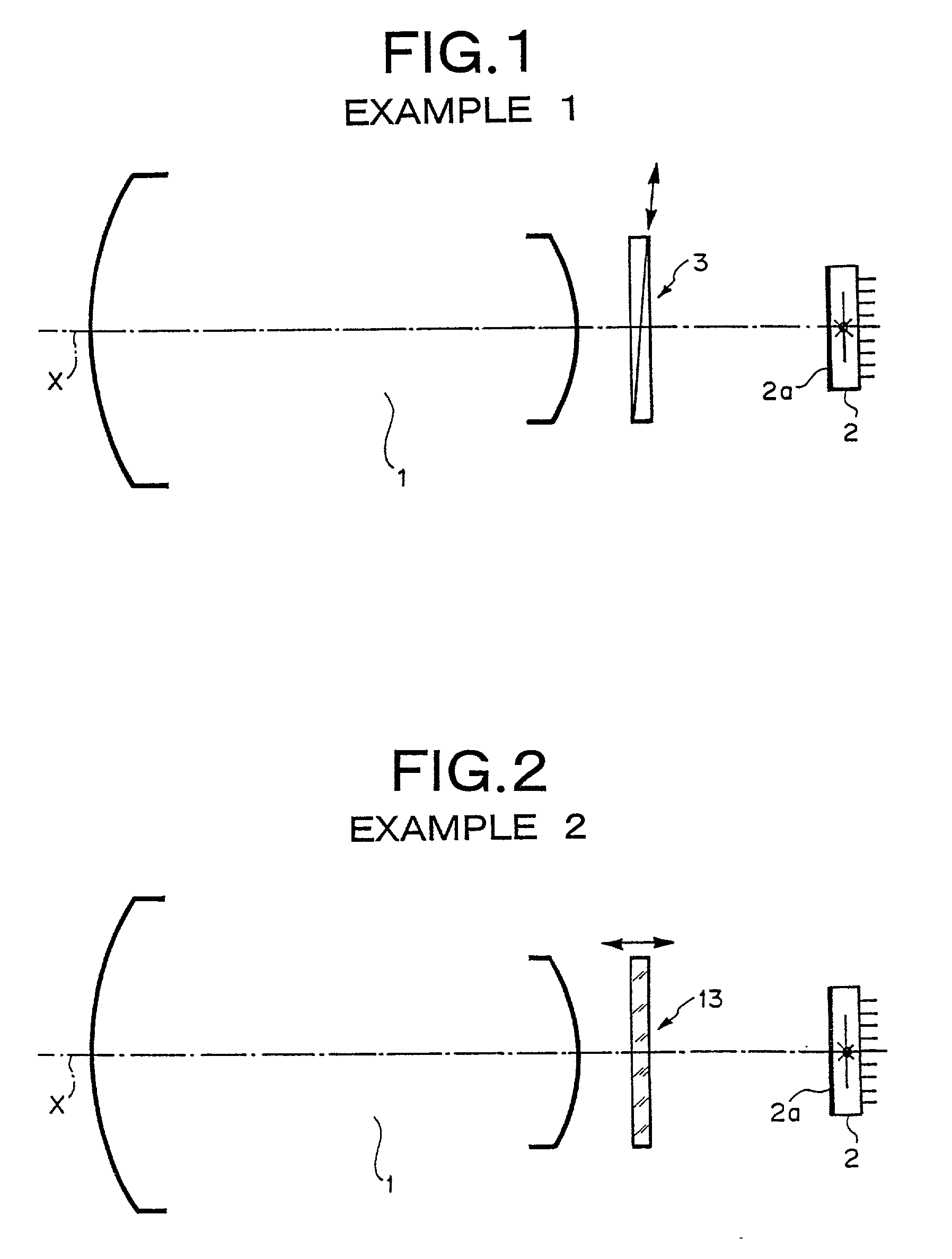
, two wedge-shaped prisms are combined together to form a parallel-plane plate, thereby forming a variable-thickness optical filter 3 whose overall thickness can be changed by means of sliding the prisms away from or close to each other along tapered surfaces of the prisms. The optical filter 3 is interposed between the photographing lens 1 and the CCD 2 along an optical axis X. In accordance with the wavelength of the light entering the photographing lens 1, the thickness of the optical filter 3 is changed, thereby correcting a shift in the focal point.

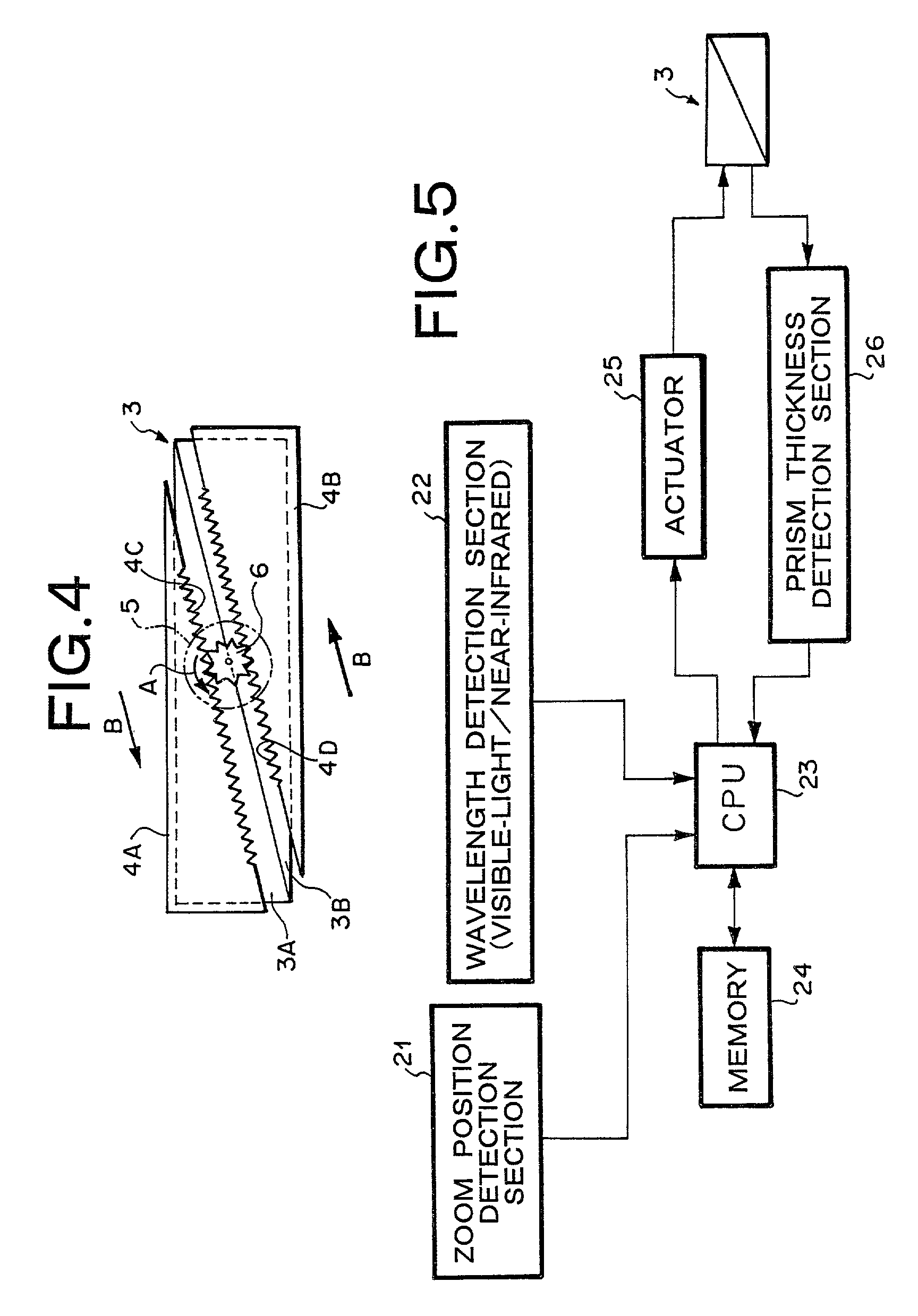
[0032] The variable-thickness optical filter 3 is slid by means of a known actuator. A thickness-variation system including the actuator will be described later.

[0033] FIG. 2 is a schematic view showing the principal construction of the dual-use visible-light / infrared image pickup device according to Example 2 of the present invention. A variable-thickness optical filter 13 according to Example 2 is formed by means of arranging two g...


PUM


Abstract

A shift in focal point due to longitudinal chromatic aberration of a photographing lens is properly corrected in accordance with various photographing conditions, by means of controlling the thickness of a variable-thickness optical filter interposed between an image pickup lens system and a solid-state image pickup element, on the basis of a correlation table defining the correlation between photographing conditions and the thickness of the variable-thickness optical filter that can correct a shift in focal point. A variable-thickness optical filter is interposed between a photographing lens system and a CCD having sensitivity ranging from the visible-light range to the infrared range. The thickness of the optical filter is changed, by means of controlling an actuator on the basis of a correlation table defining the correlation between the photographing conditions and the thickness of the variable-thickness optical filter which can correct the shift in optical focal point. The variable-thickness optical filter is formed from two wedge-shaped prisms combined together to form a parallel-plane plate, and the overall thickness of the variable-thickness optical filter can be changed, by means of moving the prisms in opposite directions while oblique lines of the prisms remain in contact with each other.

Description

[0001] This application claims the priority of Japanese Patent Application No. 2000-087774 filed on Mar. 28, 2000, which is incorporated herein by reference.[0002] 1. Field of the Invention[0003] The present invention relates to a visible-light / infrared image pickup device having sensitivity ranging from the visible light range to the infrared (IR) range, and more particularly, to a visible-light / infrared image pickup device capable of correcting a shift in focal point caused by longitudinal chromatic aberration which would arise depending on image pickup conditions.[0004] 2. Description of the Prior Art[0005] In the field of cameras using solid-state image pickup elements, a solid-state image pickup element whose spectral sensitivity extends from the visible-light range to the infrared range has recently been developed. A camera employing such a solid-state image pickup element is also known.[0006] Since infrared radiation is suitable for night photographing, attention has been pai...

Claims


Application Information

Patent Timeline
Patent Type & Authority Applications(United States)
IPC IPC(8): G02B7/28G03B3/04G02B23/12G02B26/08G03B13/32G03B15/00H04N5/225H04N5/232H04N5/33
CPCG02B23/12G02B26/0875H04N5/2254H04N5/33H04N5/332H04N23/11
Inventor YOSHIKAWA, KAZUO
Owner FUJI PHOTO OPTICAL CO LTD
Why Eureka
Try Eureka