
Method in wireless telecommunication system, system, transmitter and receiver

a wireless telecommunication system and code division technology, applied in the direction of multiplex communication, orthogonal multiplex, wireless communication, etc., can solve the problems of deterministic, difficult optimal network design, difficult network management, etc., and achieve the effect of facilitating network management and network design

Inactive Publication Date: 2001-10-18
DOMIRAS
View PDF0 Cites 65 Cited by
  • Summary
  • Abstract
  • Description
  • Claims
  • Application Information

AI Technical Summary

Benefits of technology

[0022] The invention provides the advantage that the method of the invention facilitates network management and network design especially in a situation where mobile or temporary base stations need to be added to the base station system. A further advantage of the invention is that the method of the invention creates a different long-code mask for each link between the transmitter and the receiver, which means that the code sequence used on the link is also unique. A yet further advantage of the invention is that by utilizing the method of the invention, a network or local parts of it can be installed quickly.
[0023] In the following, the invention will be described in greater detail with reference to the accompanying drawings in which
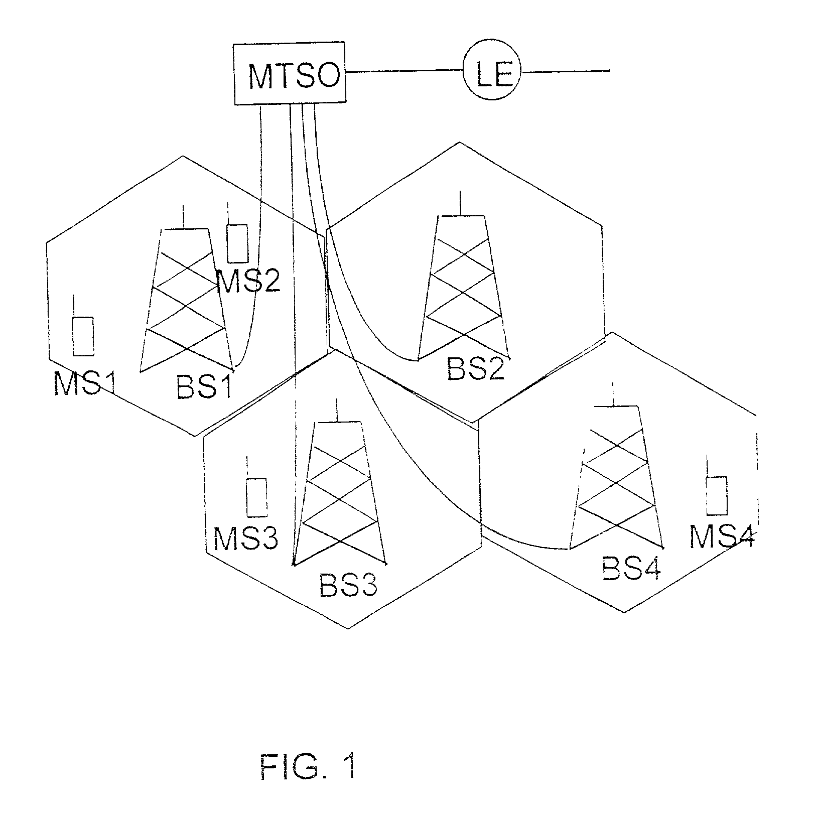
[0024] FIG. 1 shows a simplified block diagram of the structure of a mobile system,
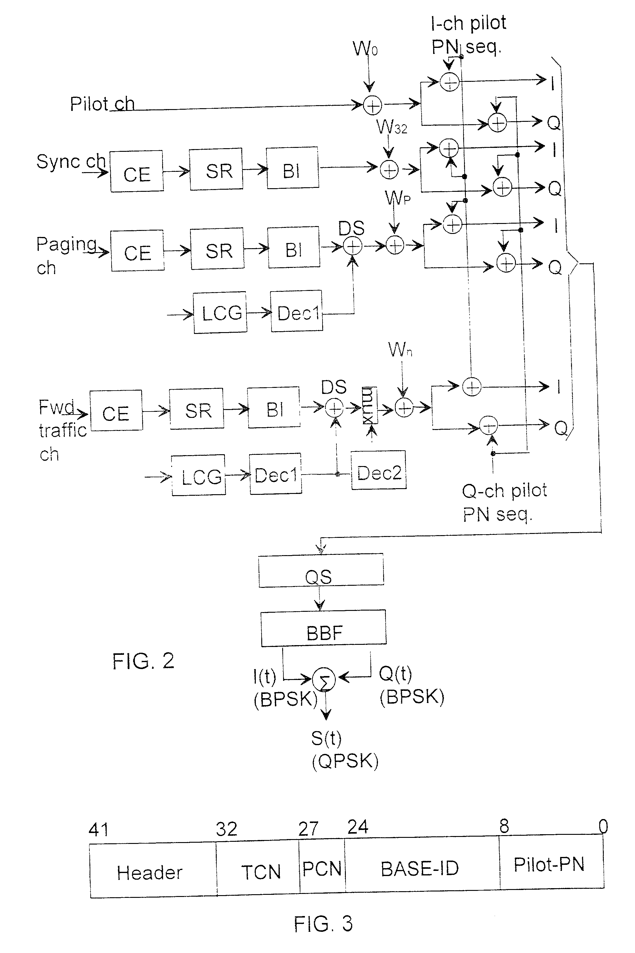
[0025] FIG. 2 shows a simplified block diagram of the code channel structure of a forward CDMA channel according to the IS-95 system,
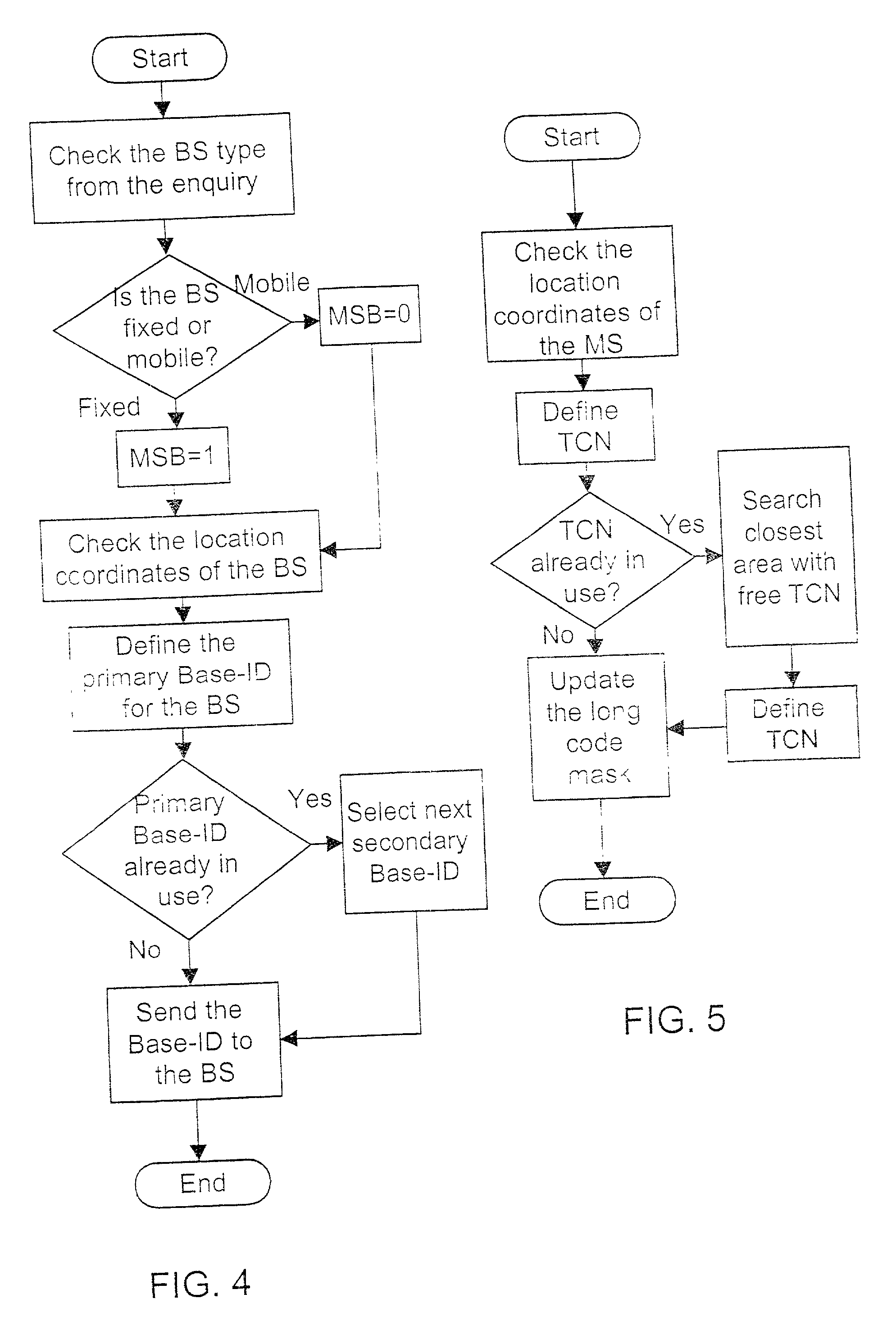
[0026] FIG. 3 shows a general bit format of the long-code mask in the IS-95 system,
[0027] FIG. 4 shows an exemplary flow chart illustrating the definition of a transmitter identifier performed by a telecommunication switching center in accordance with a preferred

Problems solved by technology

The code sequences used are pseudo-random noise sequences, i.e. the code sequences resemble random noise, but are, however, deterministic.
The procedure described above makes optimal network design difficult, because the design must take into account the cell size, the transmission power used, the number of code sequences, the number of various services, the area coverage of the cellular network, and the overlapping of the cells, etc.
The procedure described above makes network management difficult especially in a situation where it would be useful to use a mobile transmitter to provide local services.
In such a case, a mobile base station creates, in most cases, an overlapping cell with the already existing fixed cell, and network management and handover decisions become more difficult.
Further, the known method for defining code sequences slows down the installation of a network in new areas, because the code masks used and thus also the code sequences must be carefully planned so as not to produce overlapping with the already existing local area code sequences.

Method used


Image

  • Method in wireless telecommunication system, system, transmitter and receiver
  • Method in wireless telecommunication system, system, transmitter and receiver
  • Method in wireless telecommunication system, system, transmitter and receiver

Examples


Embodiment Construction

[0029] FIG. 1 shows the general structure of a mobile network used in the invention. Mobile stations (MS1 to MS4) are connected to base stations (BS1 to BS4) over a radio path. The base stations BS1 to BS4 are connected to a mobile telephone switching office (MTSO) usually through a wired connection, but the connection can also be wireless. The mobile telephone switching office is connected to a public telephone network (not shown) through a local exchange (LE). The general structure of a mobile network is known to persons skilled in the art and thus it is not necessary to describe it in greater detail herein.

[0030] In the following, the invention will be described by way of example in greater detail on the basis of FIGS. 2 and 3 with reference to the CDMA system (IS-95) used in mobile networks. It is obvious that the invention is not restricted to mobile networks only, but can be applied to any wireless telecommunication system within the scope of the accompanying claims.

[0031] In ...


PUM


Abstract

A method in a wireless telecommunication system using code division multiple access technology, which system comprises a telecommunication switching center, a transmitter and a receiver, in which method the telecommunication switching center defines an identifier for the transmitter on the basis of the location of the transmitter and the transmitter defines a traffic channel identifier for the radio link traffic channel between said transmitter and said receiver on the basis of the location of the receiver. In the system, the channels of the radio link between the transmitter and the receiver are distinguished from each other by code sequences, and the code sequences used are defined according to the location information of the transmitter and the receiver. The definition of the location information of the transmitter and the receiver is performed by means of a satellite positioning system.

Description

[0001] This invention claims priority to co-pending International Patent Application No. PCT / FI99 / 00725, filed on Sep. 7, 1999, which in turn claims priority to Finland Patent Application No. 981923, filed on Sep. 8, 1988 the specifications of each of which are incorporated herein by reference.[0002] 1. Field of the Invention[0003] The invention relates to a method in a wireless telecommunication system using code division multiple access technology, which system comprises a telecommunication switching center, a transmitter and a receiver, in which method an identifier is defined for the transmitter and a traffic channel identifier is defined for the radio link traffic channel between said transmitter and said receiver, and in which method the channels of the radio link between the transmitter and the receiver are distinguished from each other by means of code sequences. The invention also relates to a wireless telecommunication system using code division multiple access technology,...

Claims


Application Information

Patent Timeline
Patent Type & Authority Applications(United States)
IPC IPC(8): H04J13/00H04J11/00H04W64/00H04W72/04H04W88/08H04W92/10
CPCH04J13/16H04W64/00H04W72/048H04W92/10H04W72/51
Inventor MAKIPAA, RISTO
Owner DOMIRAS
Learn More