
Quadrant and anterior dental shells and method of making a multi-tooth crown or bridge

Inactive Publication Date: 2001-11-01
CROWNBEAV
View PDF0 Cites 26 Cited by
  • Summary
  • Abstract
  • Description
  • Claims
  • Application Information

AI Technical Summary

Benefits of technology

[0020] It is, therefore, an object of the present invention to simplify the fabrication, fitting, and installation of temporary and semi-permanent bridges and multi-tooth crowns.
[0021] Another object of the present invention is to make temporary and semi-permanent bridges and multi-tooth crowns that fit well and are durable enough for long-term use.
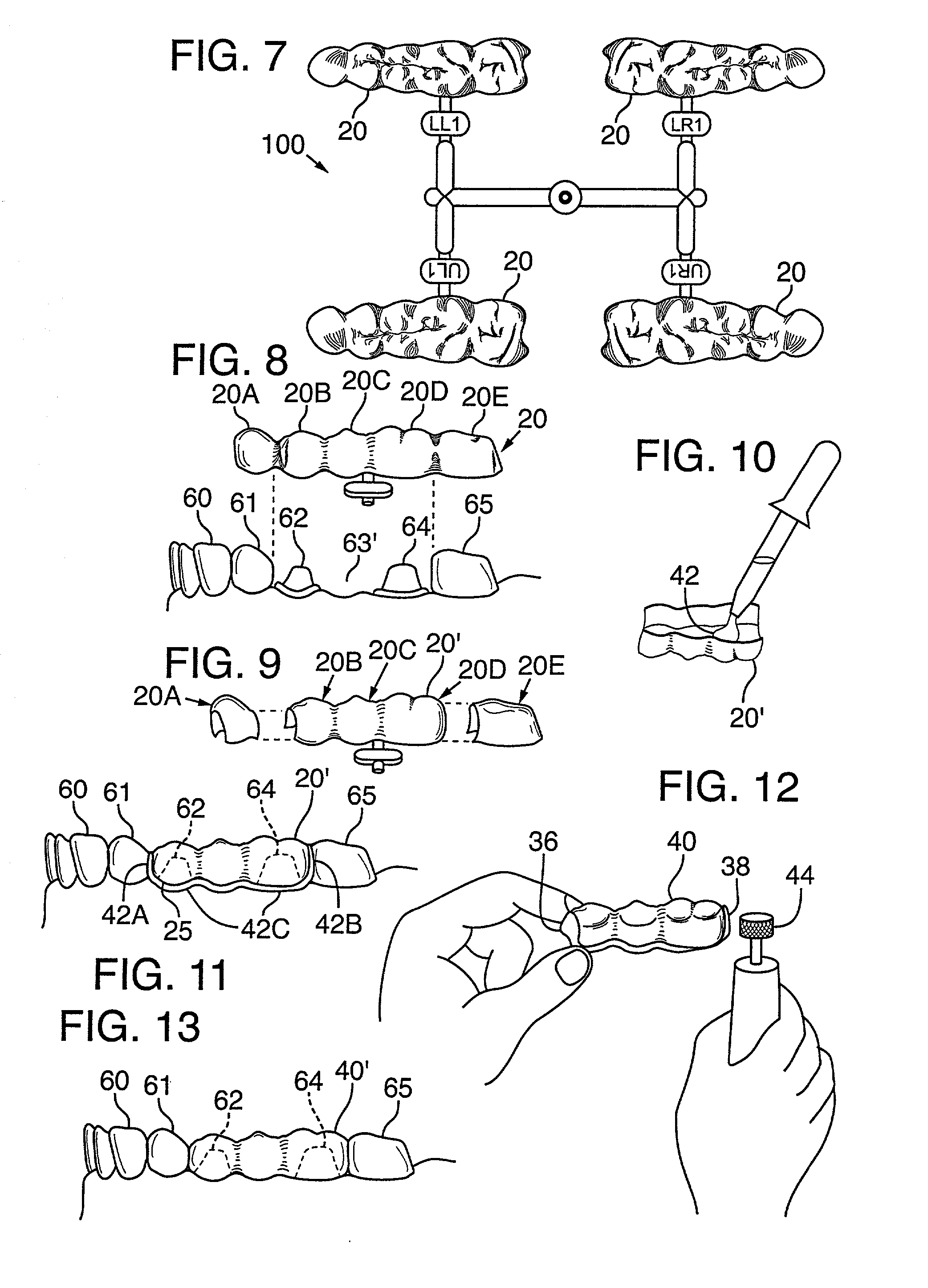
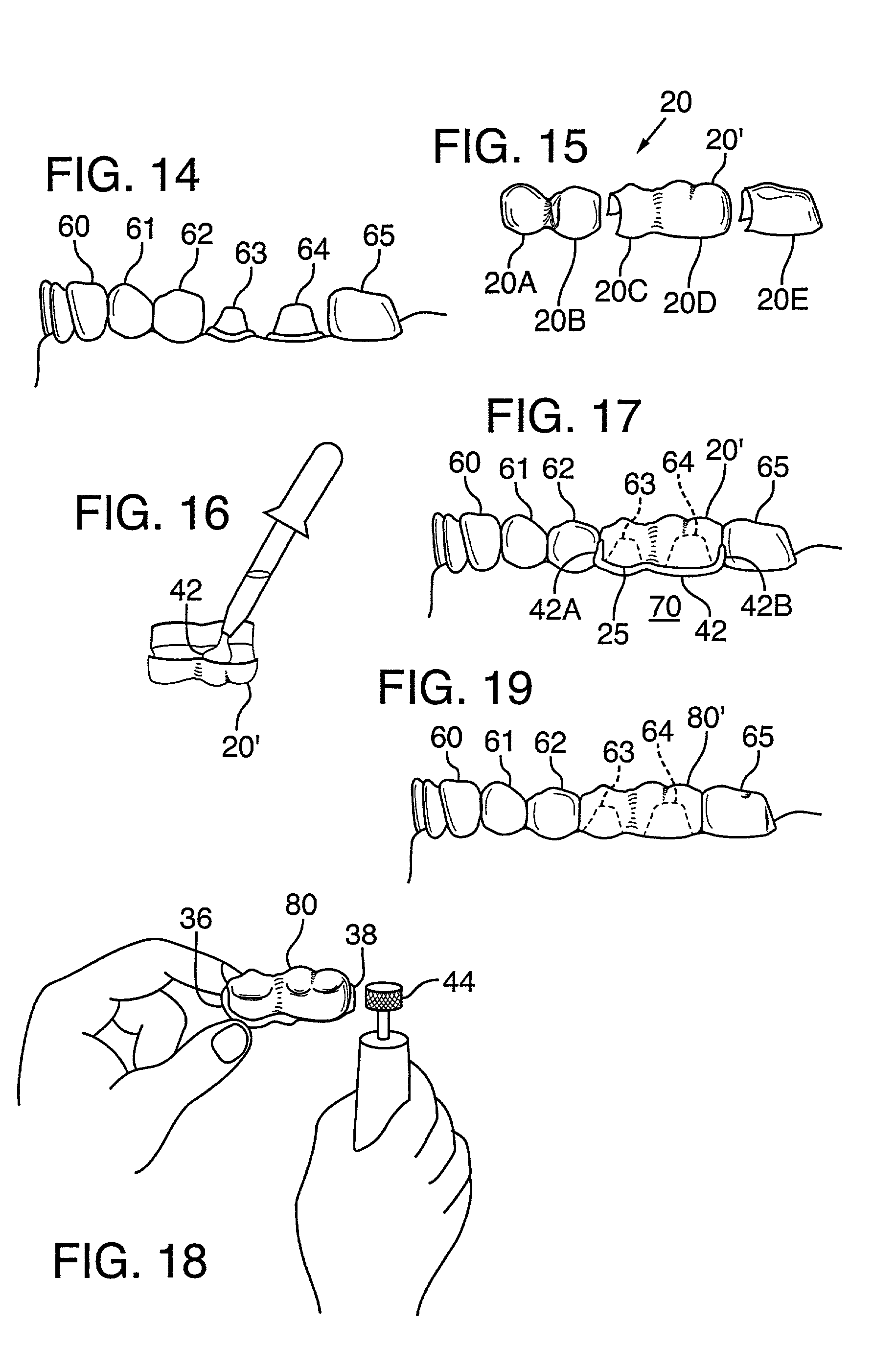
[0029] These same shells can also be used by a dentist to provide multi-tooth crowns for adjacent prepared teeth. To provide a multi-tooth temporary or provisional crown, an appropriate multi-tooth shell is selected and sectioned, if necessary, to leave a fused hollow shell section having multiple interconnected shell segments corresponding to just the prepared teeth. This shell section is then filled with resin, placed on the prepared teeth, and left there until the resin has set. Once the resin has set, the resulting unfinished crown is removed from the prepared teeth and adjusted as necessary to fit comfortably within the patient's dentition. The finished multi-tooth crown forms a composite structure is then cemented onto the prepared teeth. As an added benefit of this invention, the remaining, unused shell segments can be saved and used at another time for preparing crowns for teeth corresponding to those unused segments.

Problems solved by technology

Using prefabricated forms, as in the first technique, for example, is fast and simple, but the fit of conventional pre-formed shells is not very good.
The margins, in particular, do not fit well.
Specifically, it is hard to get good proximal contact to adjacent teeth, and the contours and occlusion are not always good.
Unfortunately, this attempted solution is expensive in terms of materials and also in terms of the time required for the dentist to pick the right shell.
Trimming and fitting is time-consuming for the dentist and the patient.
The second technique gives good contours and bite accuracy, but making an impression is time-consuming.
Furthermore, neither the strength nor the durability of temporary crowns produced by this technique are very good.
Furthermore, the impression cannot be made if the patient's tooth is already broken when initially treated.
Another main problem with the third approach is that it is very technique-sensitive.
A still further problem with this technique is that special care must be taken to ensure that the patient's mouth is not injured by the exothermal reaction involved in curing the crown material.
All of the foregoing techniques are undesirably slow.
Even the fastest of these techniques generally takes half an hour or more of work for the dentist to fit a temporary or provisional crown to a patient.
Additionally, the crowns resulting from the second and third techniques are typically not very durable and are therefore not well-suited for long-term wear.
Although the stainless steel shells of the first technique are very durable, it is more difficult to fit stainless steel shells to the patient and to grind the shell' occlusal surfaces to get a comfortable bite.
This, too, saves the dentist a great deal of time.
Despite the improvements offered by applicant's prior inventions described above, neither it, nor any of the other prior art techniques, readily facilitate the preparation of multiple crowns at the same time.
They also do not address the use of shells in preparing bridges to replace missing teeth.
Unfortunately, most present methods for constructing bridges are unduly time-consuming and complex.
Temporary bridges are typically necessary because the process of constructing the permanent bridge is time consuming.
Even preparing and installing temporary bridges, however, is generally more complex, time consuming, and expensive than desirable.
These techniques are expensive and burdensome because they require a large amount of dentist time.

Method used


Image

  • Quadrant and anterior dental shells and method of making a multi-tooth crown or bridge
  • Quadrant and anterior dental shells and method of making a multi-tooth crown or bridge
  • Quadrant and anterior dental shells and method of making a multi-tooth crown or bridge

Examples


Embodiment Construction

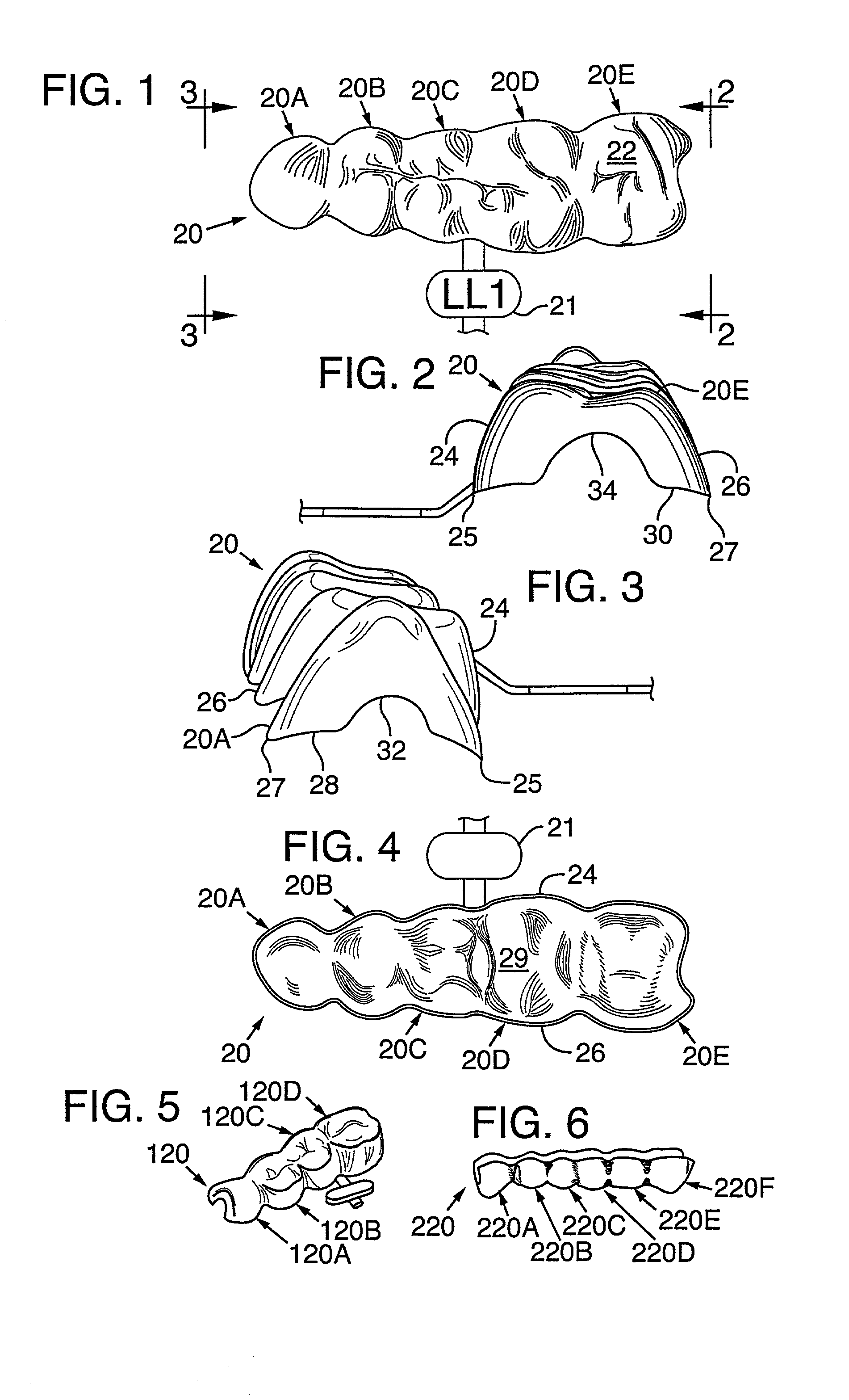
[0052] Generally, a multi-tooth shell according to this invention is an integrally molded unit having multiple single-tooth shell segments, wherein each segment corresponds to a different tooth. Each segment has an external shape approximating the buccal, lingual, and occlusal anatomy of the corresponding natural human tooth. Each segment also has an interior cavity sized to fit over a prepared tooth and to be filled with resin.

[0053] Various different tooth types can be represented by the shell segments in different multi-tooth shells. For a quadrant shell, these tooth types can include cuspids, bicuspids, and molars. For an anterior shell, they can include cuspids, canines, and incisors. For a hybrid quadrant / anterior shell, these shell segments can correspond to any combination of quadrant and anterior teeth in the order normally occurring in a patient's dentition.

[0054] Quadrant shells are preferably formed with segments corresponding to four or five individual teeth within a pa...


PUM


Abstract

A quadrant and / or anterior shell for making a bridge or multi-tooth crown includes a plurality of integrally formed shell segments. Each shell segment corresponds to a different tooth in the respective quadrant and / or anterior region. Each shell has an occlusal surface, formed on a top wall, that replicates the occlusal surface of a natural tooth. A method of forming bridges or crowns using such shells includes selecting or sectioning off an appropriate section of the shell. The selected shell section is filled with resin. The shell section is positioned over prepared teeth, and, in the case of a bridge, also over a gap in the patient's dentition. Resin extrudes from mesio-distal sides and gingival margins of the shell section to form good proximal and gingival contacts. Once the resin has set, the resin and shell section are shaped to form the final crown or bridge.

Description

RELATED APPLICATION DATA[0001] Priority is claimed from Ser. No. 60 / 190,127 filed Mar. 16, 2000.BACKGROUND OF THE INVENTION[0002] This invention relates generally to fabricating temporary and semi-permanent bridges and to temporization where multiple teeth are involved. More particularly, this invention extends the concepts for constructing and using shells for temporary and provisional crowns, as disclosed in Applicant's prior patent applications (including U.S. Pat. No. 6,068,481, U.S. Ser. No. 09 / 178,023 filed Oct. 23, 1998, PCT / US98 / 22813, and Ser. No. 60 / 131,817, filed Apr. 29, 1999, each herein incorporated by reference), to the creation of temporary and semi-permanent bridges and multi-tooth crowns.[0003] Applicant's prior applications disclose flexible dimension crown shells and methods of making temporary and long-term provisional dental crowns using such shells. As noted in those applications, three primary methods have been used for fabricating temporary and provisional c...

Claims


Application Information

Patent Timeline
IPC IPC(8): A61C5/08A61C13/00A61C13/003
CPCA61C5/002A61C5/08A61C13/0003A61C13/26A61C13/225A61C5/20A61C5/70A61C5/73
Inventor WORTHINGTON, MARK L.
Owner CROWNBEAV
Learn More