Lens blanks for ophthalmic elements

Inactive Publication Date: 2001-11-08
VISION EASE LENS
View PDF0 Cites 8 Cited by
  • Summary
  • Abstract
  • Description
  • Claims
  • Application Information

AI Technical Summary

Benefits of technology

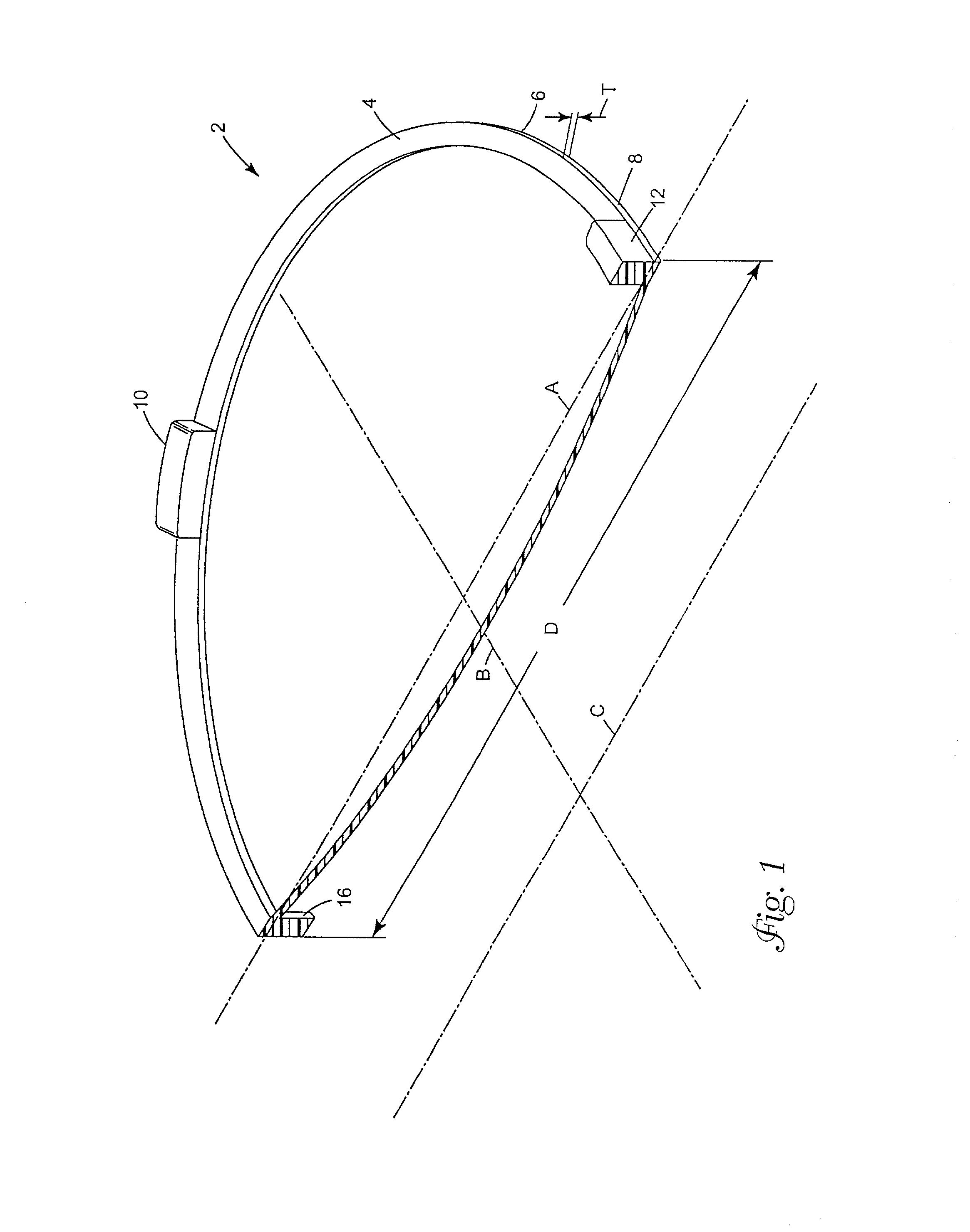
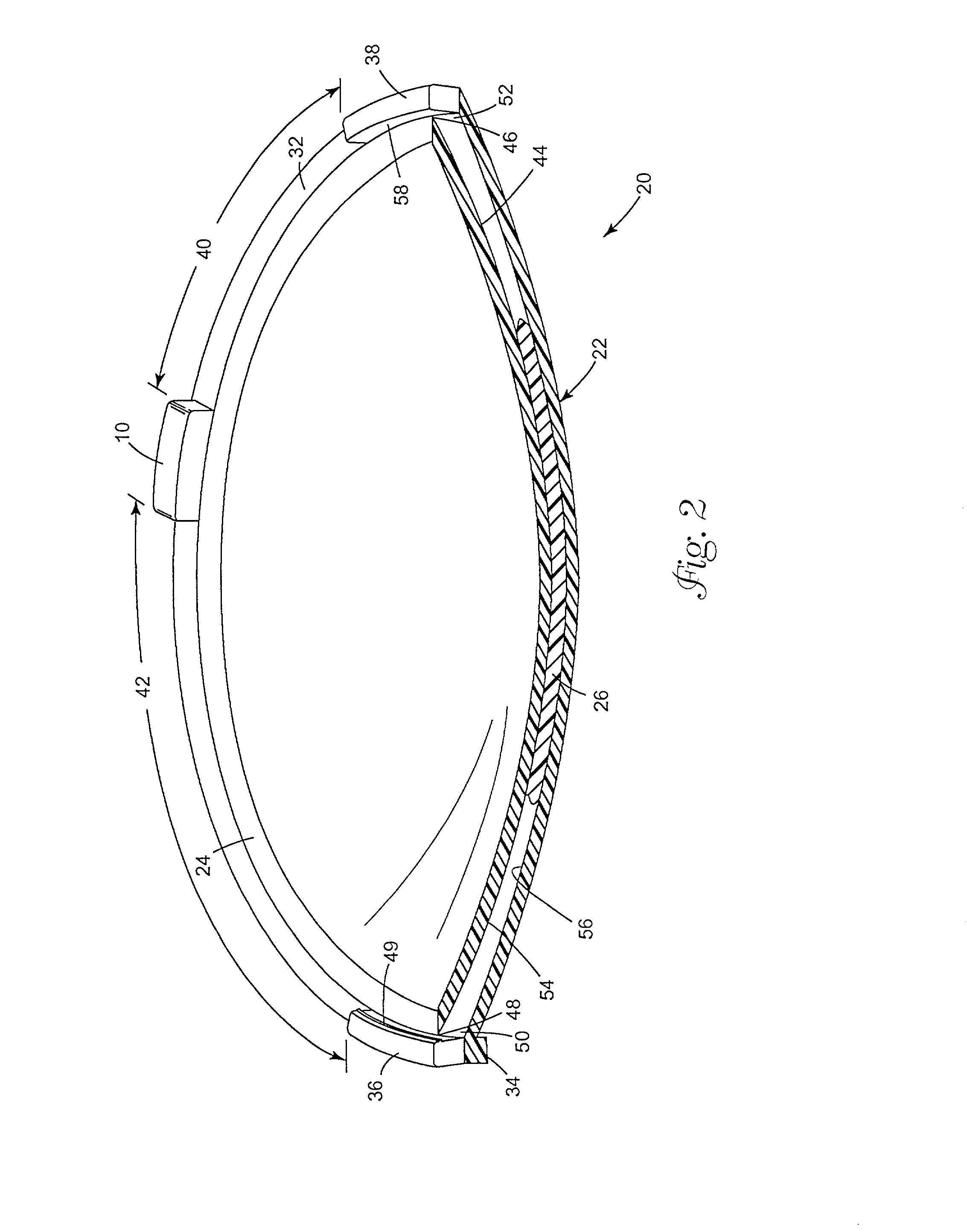
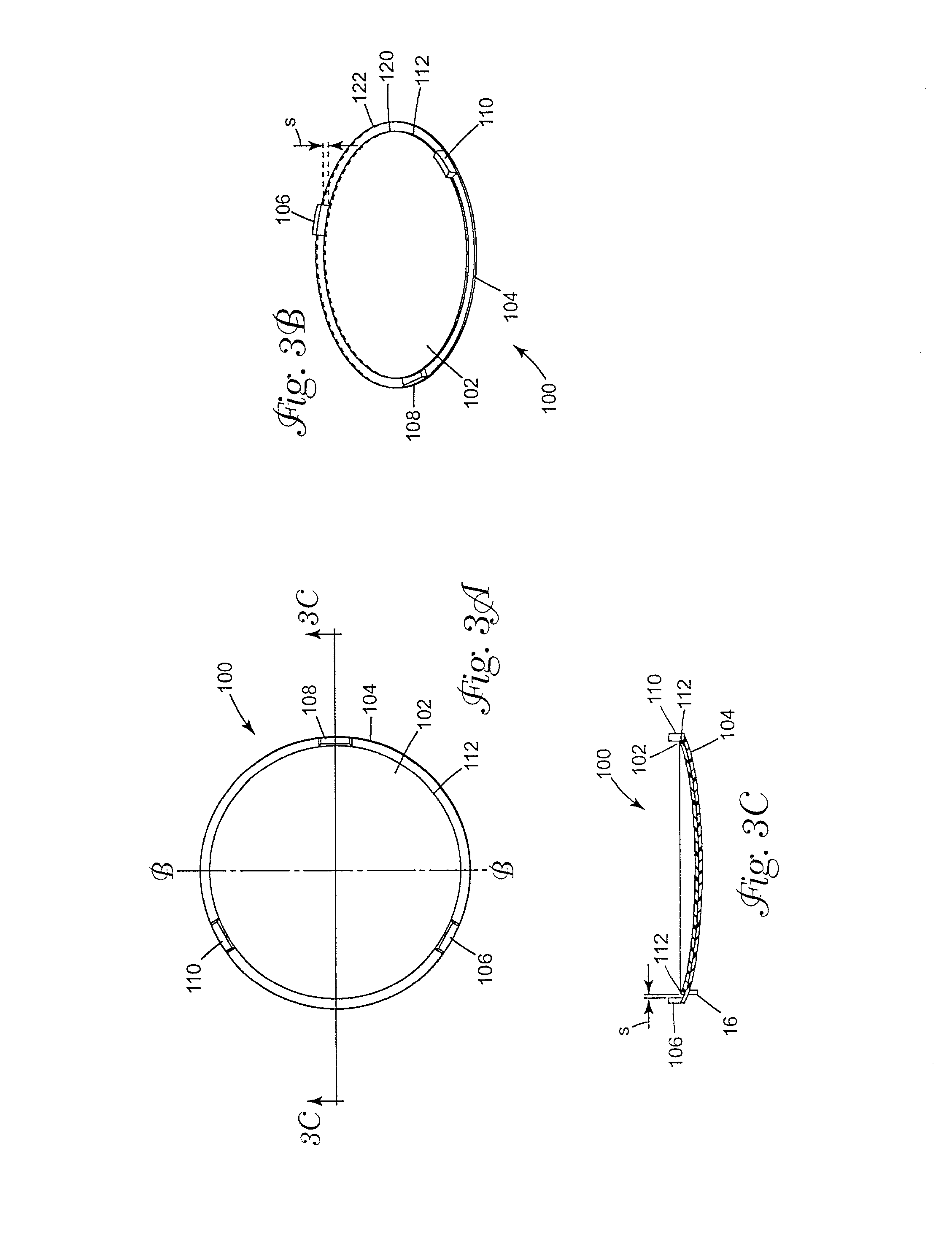
0071] The projections should be spaced around the edge, rather than being only within a single quadrant or a single half of the circumference of the optical element. Where the front optical element is approximately round, the projections should be spaced approximately equally around the circumference. For example, the projections may be spaced at about 120 degrees (.+-.15 degrees) with a circular cross-section, or 90 degrees (.+-.15 degrees). The projections may have roughened surfaces, ledges, lips, indentations, projections or the like to assist in restricting movement of the edge of the back lens against these posts or projections.
0072] To assist in the identification of lenses to be chosen for lamination, strippable polymeric or paper films of different color or other identifying features may be placed over each type of lens depending upon its optical (e.g., dioptic) properties. For example, not only may films (including paper and polymeric film) be adhered to a surface

Problems solved by technology

Especially when the desired composite lens includes a cylindrical component that must be properly oriented to correct for astigmatism and a bifocal or progressive focal region that must be properly positioned for reading purposes, the existing methods and equipment have fallen short of the desired optical accuracy.
Existing laminating equipment, for example, does not readily accommodate eccentric positioning and bonding of the front and rear lenses, which can be necessary in some cases.
Also, existing methods and equipment have been inconvenient in operation and have put the desirable accuracies beyond practical reach for some composite eyeglass lenses.
Polycarbonate's potential advantages over cast allylics were virtually offset by comparatively poorer abrasion resistance performance and poorer tintability, as well as re

Method used


Image

  • Lens blanks for ophthalmic elements
  • Lens blanks for ophthalmic elements
  • Lens blanks for ophthalmic elements

Examples


Embodiment Construction

[0073] The lens wafers were molded consisting of 80 mm polycarbonate PAL front wafers and 75 mm polycarbonate SV back wafers. Each of the wafers was molded with a 0.8mm + / -0.10 mm center thickness. Three tabs were located 120.degree. apart around the outside edge of the back of the front wafers. These tabs were used to align the center of the two lens wafers.

[0074] Once molded, the wafers were checked for through power on the Humphry and the center thickness measured. The results are recorded in Tables 1 and 2 below.

1TABLE 1 Front wafer characteristics Center thickness, Lens ID Humphry base power Humphry add power c.t., (mm) 84412 -0.87 .times. -0.09 1.15 0.87 83412 -0.92 .times. 0.00 1.18 0.86

[0075]

2TABLE 2 Back wafer characteristics Center thickness, c.t., Lens ID Humphry base power (mm) LMA4.97 / 4.98 .times. 0.00 -0.3 .times. 0.00 0.84 LMA4.97 / 4.98 .times. 0.00 -0.1 .times. 0.00 0.84 LMA4.97 / 4.98 .times. 0.00 -0.02 .times. 0.00 0.87 LMA4.97 / 4.98 .times. 0.00 -0.01 .times. 0.00 0.8...


PUM

PropertyMeasurementUnit
Fractionaaaaaaaaaa
Fractionaaaaaaaaaa
Diameteraaaaaaaaaa

Abstract

A polymeric front optical element blank is provided which may be laminated to a rear optical element blank. The polymeric front blank comprises an optical element having an exterior convex surface and an interior concave surface, with an edge between the exterior convex surface and the interior concave surface. The optical is provided with at least two projections which extend away from and higher than the edge on a side of the optical element having the concave surface. These projections assist in aligning an back optical element during lamination so that the two lenses will not move out of optical registry during lamination, especially where centrifugal forces are used to spread an adhesive between the front and rear lenses. It is preferred that there are at least three projections extending away from and higher than the edge on a side of the optical element having the concave surface. A particularly desirable and preferred process for using these lenses comprises the steps of: a) positioning a first optical element blank according to the invention having an interior surface and an exterior surface, b) applying a photopolymerizable adhesive composition on the interior surface of the optical element blank, the photopolymerizable adhesive composition being curable by UV radiation having a wavelength of between 385 and 410 nm, and the maximum spectral sensitivity of the photopolymerizable composition being within 15 nm of said UV radiation having a wavelength of between 385 and 410 c) positioning a second optical element blank having an interior surface and an exterior surface on the polymerizable adhesive composition with an interior face in contact with the polymerizable adhesive composition to form a prelaminated association, wherein at least one of the first and second optical element blanks absorbing at least 95% of any ultraviolet radiation component between 180 and 380 nm of incident radiation and allows at least 30% transmittal of at least one wavelength of ultraviolet radiation between 385 and 410 nm, and d) irradiating the prelaminated association with UV radiation having a significant component between 385 and 410 nm through at least one of the first and second optical element blanks to cure the adhesive and to laminate the first and second optical elements.

Description

[0001] 1. Field of the Invention[0002] The present invention relates generally to lens blanks for forming ophthalmic elements and the lamination of thermoplastic molded articles in the formation of ophthalmic elements. The invention is particularly designed to provide a finished multifocal or progressive lens with anti-reflective or abrasion resistant coatings at a commercial shop in less than twenty minutes.[0003] 2. Background of the Art[0004] The present invention finds utility in a range of materials to be joined by adhesive securement, and it is applied most advantageously to molded thermoplastic articles such as lenses, especially ophthalmic lenses, and optical disks.[0005] Lenses are used for a wide variety of purposes. For example, microscopes, telescopes, magniying glasses and other optical instruments, as well as ophthalmic spectacles, employ lenses. The following discussion focuses on the most preferred embodiment of the present invention, ophthalmic lenses.[0006] Vision-...

Claims


Application Information

Patent Timeline
IPC IPC(8): B29C65/48B29D11/00G02C7/02
CPCB29D11/0073G02C7/02B29C66/452Y10T428/21B29C66/545B29C65/4845Y10T428/219B29L2011/0016B29C65/1406B29C65/1409B29C66/71B29C66/73161
Inventor BLOMBERG, CHRISLEVIN, GERTBHALAKIA, SUJAL
Owner VISION EASE LENS
Why Eureka
Try Eureka