
Magnetic tape apparatus

a technology of magnetic tape and tape loop, which is applied in the field of magnetic tape loop, can solve the problems of limited speed up of rotation and considerable time required

Inactive Publication Date: 2001-11-22
FUNAI ELECTRIC CO LTD
View PDF0 Cites 6 Cited by
  • Summary
  • Abstract
  • Description
  • Claims
  • Application Information

AI Technical Summary

Benefits of technology

[0046] According to the invention as in aspect 1, the fast feed and the rewind of the magnetic tape can be finished in a short time, because the rotation speed of the pay-off reel table or the roll-up reel table can be increased by the speed increasing mechanism in the fast feed mode and the rewind mode.[0047] According to the invention as in aspect 2, in the fast feed mode and the rewind mode, the rotation speed of the pay-off reel table or the roll-up reel table can be increased due to the gear ratio between the large diametered gear and the small diametered gear. Moreover, because the structure of the speed increasing mechanism is simple, the magnetic tape apparatus is difficult to be broken and can be manufactured at a low cost.[0048] According to the invention as in aspect 3, in the fast feed mode and the rewind mode, by meshing the large high speed gear integrally formed with the movable rotary body with the intermediate gear, the rotation speed of the pay-off reel table or the roll-up reel table can be further increased.[0049] According to the invention as in aspect 4, by meshing the large low speed gear provided on the movable rotary body with the driven gear, the speed increasing mechanism can be switched also to the play back mode and the play back rewind mode and can be conveniently used.[0050] According to the invention as in aspect 5, by switching the mode from the fast feed mode and the rewind mode to the stop mode, the movable rotary body is set in the neutral position, thereby to instantaneously interrupt the rotary drive force of the drive gear. Therefore, the magnetic tape can be prevented from being excessively rolled up around the pay-off reel table or the roll-up reel table.

Problems solved by technology

However, since a speed increasing function is not provided, there has been a drawback that speed up of the rotation is limited, and a considerable time is required for the fast feed and the rewind of the magnetic tape T.

Method used


Image

  • Magnetic tape apparatus
  • Magnetic tape apparatus
  • Magnetic tape apparatus

Examples


Embodiment Construction

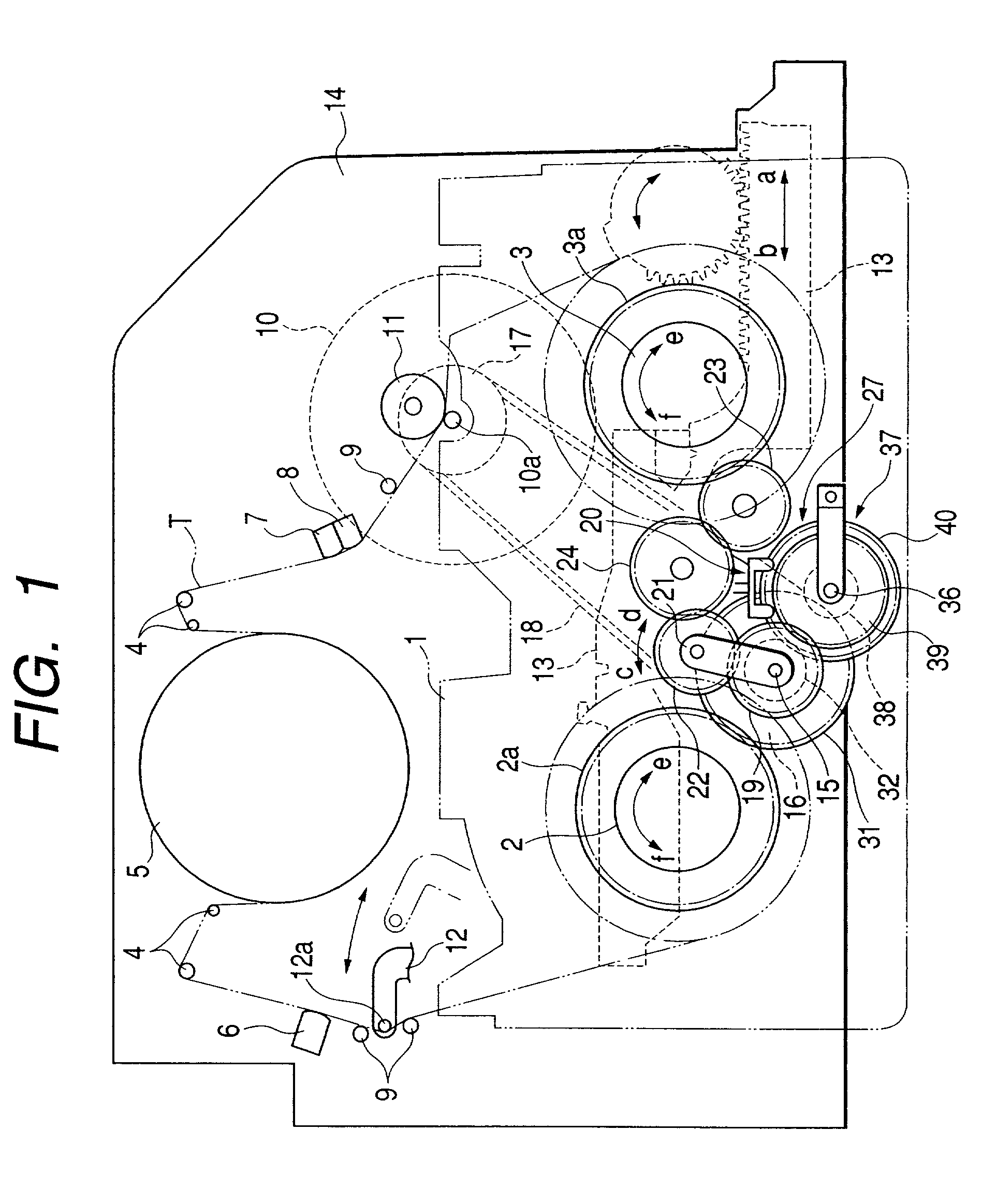
[0033] FIG. 1 shows a magnetic tape apparatus according to an embodiment of the invention, in which a speed increasing mechanism 27 is provided in an opposed relation to the pulley 16. Same parts as those of the prior art as shown in FIG. 9 will be represented by the same reference numerals and description of the parts will be omitted.

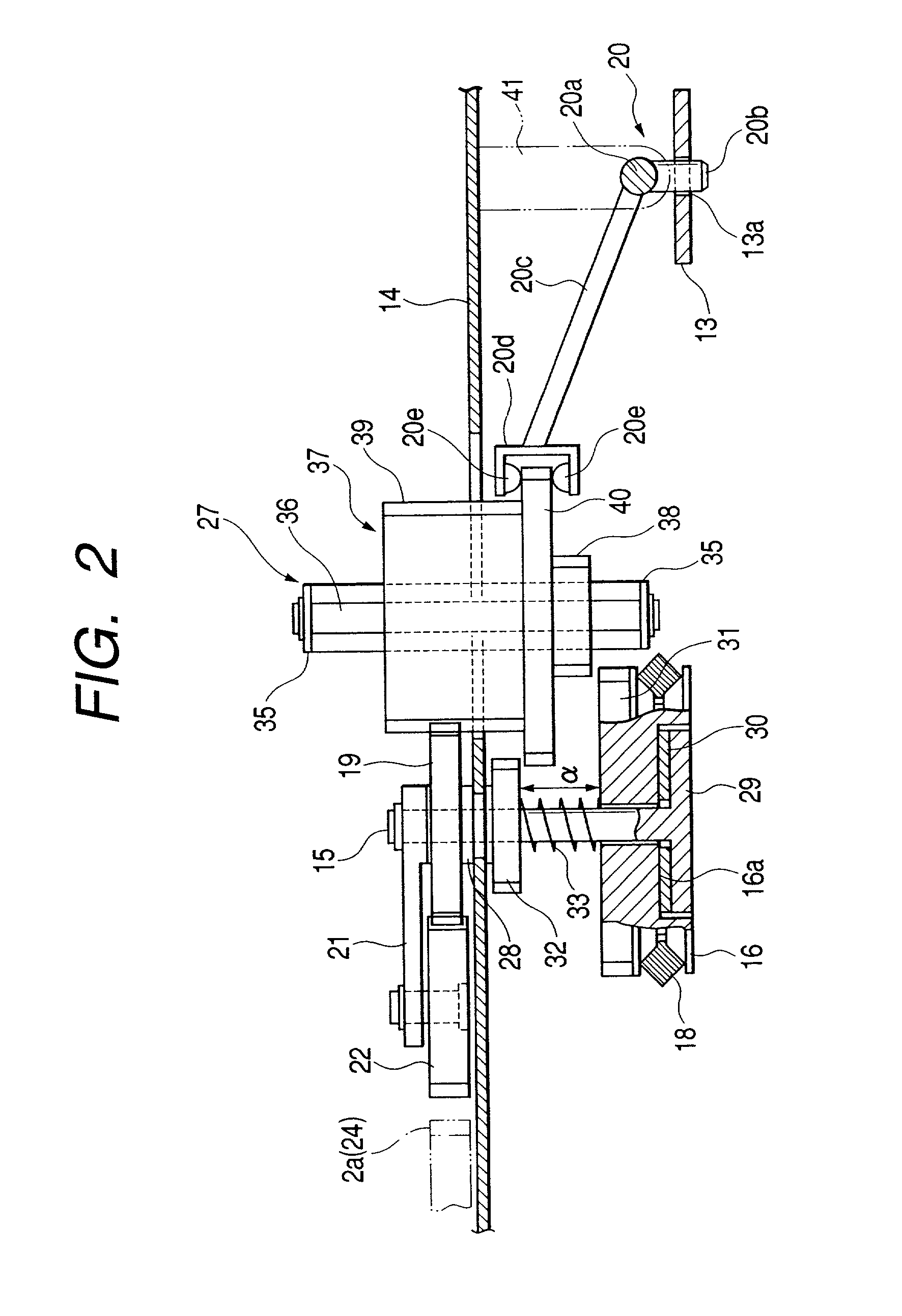
[0034] As shown in FIG. 2, the aforesaid pulley 16 is rotatably mounted around the pivotal shaft 15 which is pivotally supported on the chassis 14 by way of a bearing 28. A concave bottom face 16a formed in a lower face of the pulley 16 is releasably engaged with a disc 29 which is provided at a lower end of the pivotal shaft 15 by way of a friction plate (slip mechanism) 30 made of felt or the like which has a large friction resistance. A drive gear 31 is integrally formed at an upper end of the pulley 16.

[0035] As shown in FIG. 2, a driven gear 32 is fixed to the pivotal shaft 15 at a determined distance .alpha. from the drive gear 31. The pulley 16 ...


PUM

PropertyMeasurementUnit
diameteraaaaaaaaaa
speedaaaaaaaaaa
pressureaaaaaaaaaa

Abstract

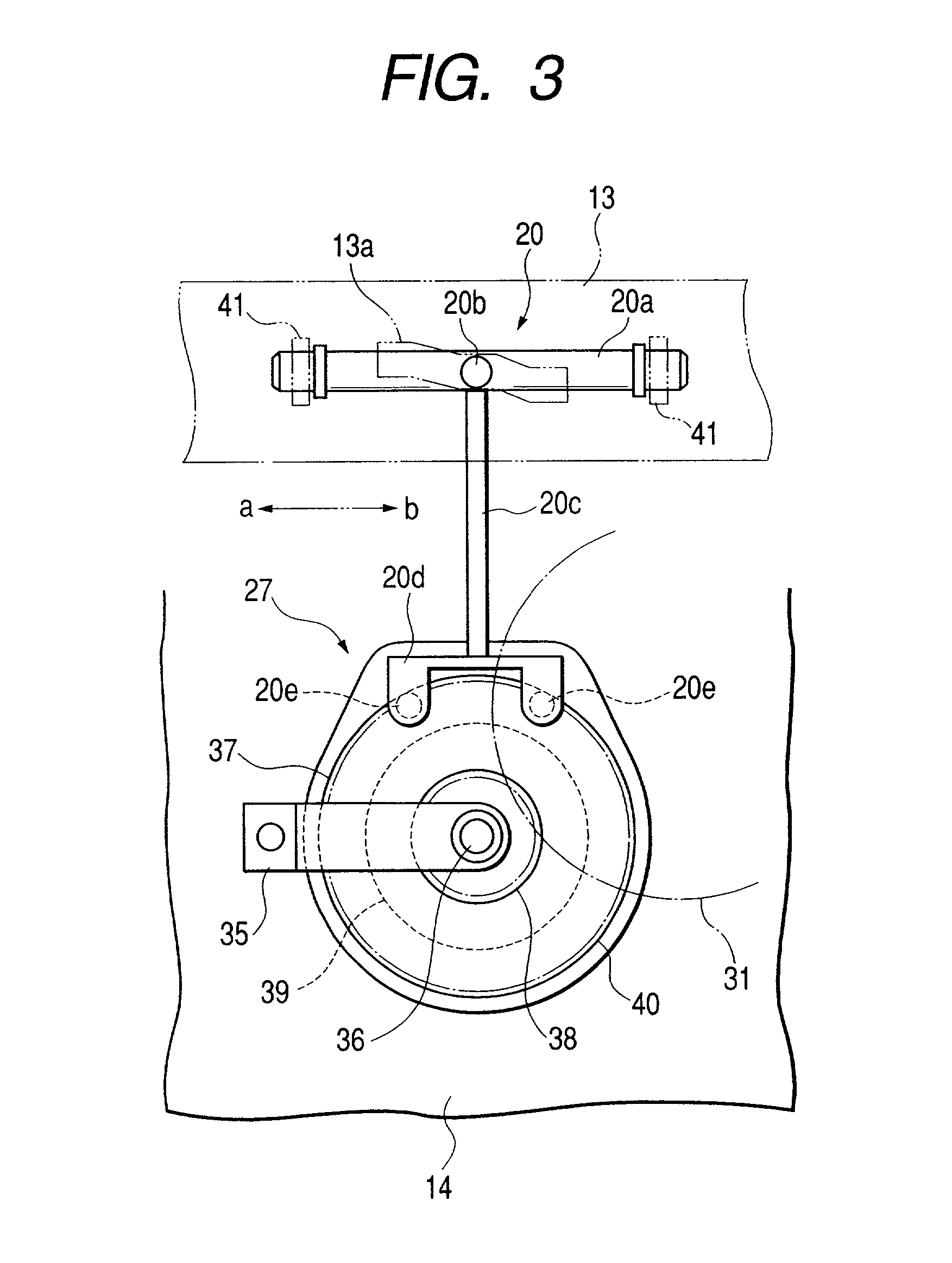
A magnetic tape apparatus has an intermediate gear 19 meshed with an idler gear 22 which is releasably meshed with both a pay-off reel table 2 and a roll-up reel table 3, a drive gear 31 rotatably driven by a capstan motor 10, a driven gear 32 releasably meshed with the drive gear 31 by way of a friction plate, a clutch mechanism 20, and a speed increasing mechanism 27. The speed increasing mechanism 27 has a movable rotary body 37 rotatably mounted around a support shaft 36 and adapted to reciprocate along an axis of the support shaft 36 by means of the clutch mechanism 20. The movable rotary body 37 is provided with a small diametered gear 38 and a large diametered gear 39. In a fast feed mode and a rewind mode, the small diametered gear 38 is meshed with the drive gear 31 while the large diametered gear 39 is meshed with the intermediate gear 19.

Description

[0001] 1. Technical Field to which the Invention Belongs[0002] The present invention relates to a magnetic tape apparatus intended to attain a high speed operation in a fast feed mode and a rewind mode.[0003] 2. Related Art[0004] As the prior art of the magnetic tape apparatus, there have been such examples as one disclosed in the Unexamined Japanese Patent Application Publication No. Hei 5-298783. One of the examples will be described referring to FIG. 9. Reference numeral 1 denotes a tape cassette, 2 denotes a pay-off reel table engaged with a pay-off reel of the tape cassette 1, 3 denotes a roll-up reel table engaged with a roll-up reel of the tape cassette 1, 4 denotes movable guide posts for winding a magnetic tape T drawn out from the tape cassette 1 around a head cylinder 5, 6 denotes an all width erase head, 7 denotes a voice erase head, 8 denotes a voice control head, 9 denotes stationary tape guide posts, 10 denotes a capstan motor for rotating a capstan 10a in a normal an...

Claims


Application Information

Patent Timeline
Patent Type & Authority Applications(United States)
IPC IPC(8): G11B15/44
CPCG11B15/444
Inventor SAWAI, KUNIOHAMABATA, HIROSHIYOKOTA, KATSUYUKI
Owner FUNAI ELECTRIC CO LTD
Learn More