Linear motion unit

a technology of motion unit and linear motion, which is applied in the direction of bearings, toothed gearings, shafts, etc., can solve the problems of affecting the dispensing process, and affecting the dispensing effect of the rod surface,

Inactive Publication Date: 2001-11-29
REXROTH STAR
View PDF0 Cites 5 Cited by
  • Summary
  • Abstract
  • Description
  • Claims
  • Application Information

AI Technical Summary

Problems solved by technology

A major disadvantage of this known linear motion unit is the small active lubricating length of its lubricating elements, which results in a high contact pressure of the lubricating elements and correspondingly severe wear of the polymer foam material.
In addition, all dirt wiped from the surface of the rod is deposited in the pores of the polymer foam material, a clogging it.
This can impede the dispensing of lubricant and can also lead to hardening of the polymer foam material, both of which impair adequate lubricating contact of the lubricating elements with the surface of the rod.

Method used


Image

  • Linear motion unit
  • Linear motion unit
  • Linear motion unit

Examples


Embodiment Construction

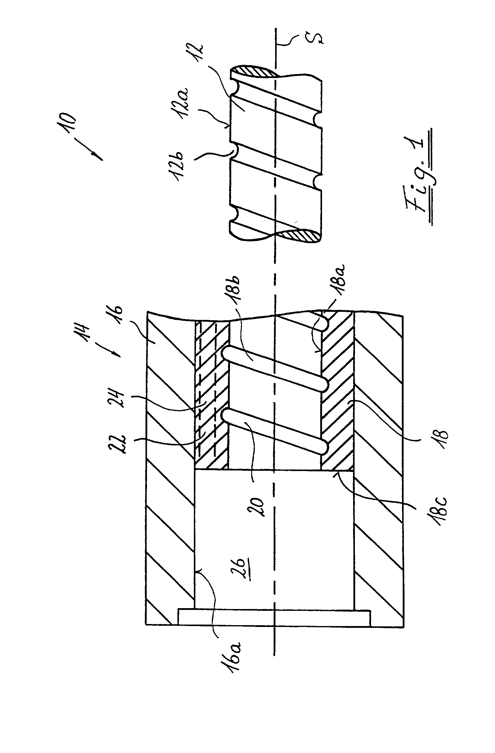
[0040] FIG. 1 shows a roller spindle drive as an example of a linear motion unit according to the invention, labeled overall as 10. It comprises a threaded spindle 12, with a spindle axis S, and a guide carriage 14 which travels back and forth along the threaded spindle 12 in the same direction as the spindle axis S and which serves to attach a functional unit (not shown) that is moved by the roller spindle drive 10. The guide carriage 14 comprises a guide carriage main section 16 and a threaded nut unit 18 that is separate from the guide carriage main section 16 and is placed in an axial passage 16a of the guide carriage main section 16 such that it cannot rotate relative thereto.

[0041] One or more spindle grooves 12b are formed in the outer circumferential surface 12a of the threaded spindle 12. The number of spindle grooves 12b that are helically coaxial to one another determines whether the threaded spindle 12 is a single-threaded or multiple-threaded spindle. Formed in the inne...


PUM


Abstract

A linear motion unit (10) includes a runner that is arranged so as to be movable back and forth on a rod along the rod's axis (S), and at least one lubricating device (28) surrounding the rod at least partially. The lubricating device (28) includes at least one lubricating element (32) that stands in lubricating contact with the rod, and at least one lubricant reservoir (34) that is carried by the runner. In accordance with the invention, the lubricant reservoir (34) is arranged radially outside the lubricating element (32) with respect to the axis (S) of the rod.

Description

BACKGROUND OF INVENTION[0001] 1. Field of the Invention[0002] The invention relates to a linear motion unit having a runner that is arranged so as to be movable back and forth on a rod along the rod's axis, and also having at least one lubricating device which at least partially surrounds the rod and which includes at least one lubricating element that stands in lubricating contact with the rod and at least one lubricant reservoir that is immovably joined to the runner.[0003] 2. The Prior Art[0004] Such a linear motion unit is known, for example from EP 0,874,172 A1. In this linear motion unit embodied as a roller spindle drive, two lubricating devices are arranged on the axial ends of the runner assembly and axially contiguous thereto. Each lubricating device is composed of a lubricating element of a polymer foam that contains lubricant and that is in lubricating engagement with the threaded spindle. In addition, each lubricating device has a lubricant reservoir that is axially adj...

Claims


Application Information

Patent Timeline
Patent Type & Authority Applications(United States)
IPC IPC(8): F16H25/22F16H25/20F16H25/24F16H57/04F16N7/12F16N7/24
CPCF16H25/20Y10T74/18744F16H57/0497F16H57/0406
Inventor KELLER, BERNHARD
Owner REXROTH STAR
Why Eureka
Try Eureka