Taking lens device

a technology of a lens and a lens body, which is applied in the field of taking lens devices, can solve the problems of large aberrations, unsuitable zoom lenses for further improvement for higher performance, and difficult to achieve higher performance necessitated,

Inactive Publication Date: 2001-11-29
MINOLTA CO LTD
View PDF0 Cites 45 Cited by
  • Summary
  • Abstract
  • Description
  • Claims
  • Application Information

AI Technical Summary

Problems solved by technology

H5-341189, mentioned above, the first lens unit is kept stationary during zooming, and therefore this zoom lens is unfit for further improvement for higher performance necessitated by the trend toward higher zoom ratios and smaller image-sensor pixel pitches.
H10-111457, mentioned above, the first lens unit is moved during zooming, but the individual lens units, in particular the first and second lens units, are given strong optical powers and thus cause large aberrations.
This makes it difficult to achieve higher performance necessitated by the trend toward higher zoom ratios and smaller image-sensor pixel pitches.
In addition, a configuration including a positive-negative-positive-negative sequence, in which the fourth lens unit is negative, is somewhat inferior in compactness to a positive-negative-positive-positive configuration.
If the lower limit of conditional formula (1) were to be transgressed, the optical power of the first lens unit Gr1 would be too strong, and thus it would be difficult to eliminate spherical aberration, in particular, at the wide-angle end W. By contrast, if the upper limit of conditional formula (1) were to be transgressed, the optical power of the first lens unit Gr1 would be too weak, and thus it would be difficult to achieve satisfactory compactness, in particular, at the telephoto end T.
This would spoil the compactness of the lens barrel structure as a whole.
As a result, it would be difficult to eliminate the aberrations that would occur in the third lens unit Gr3.
As a result, it would be impossible to realize a compact zoom lens system.

Method used


Image

  • Taking lens device
  • Taking lens device
  • Taking lens device

Examples


Embodiment Construction

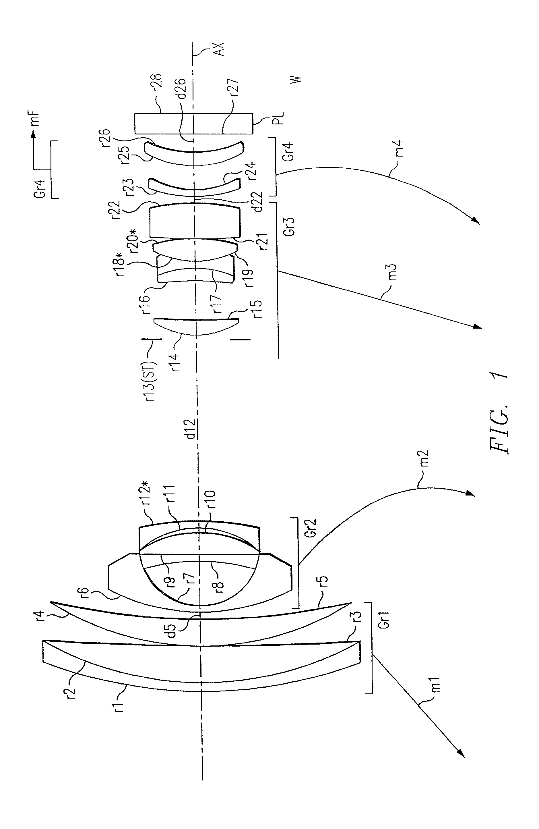
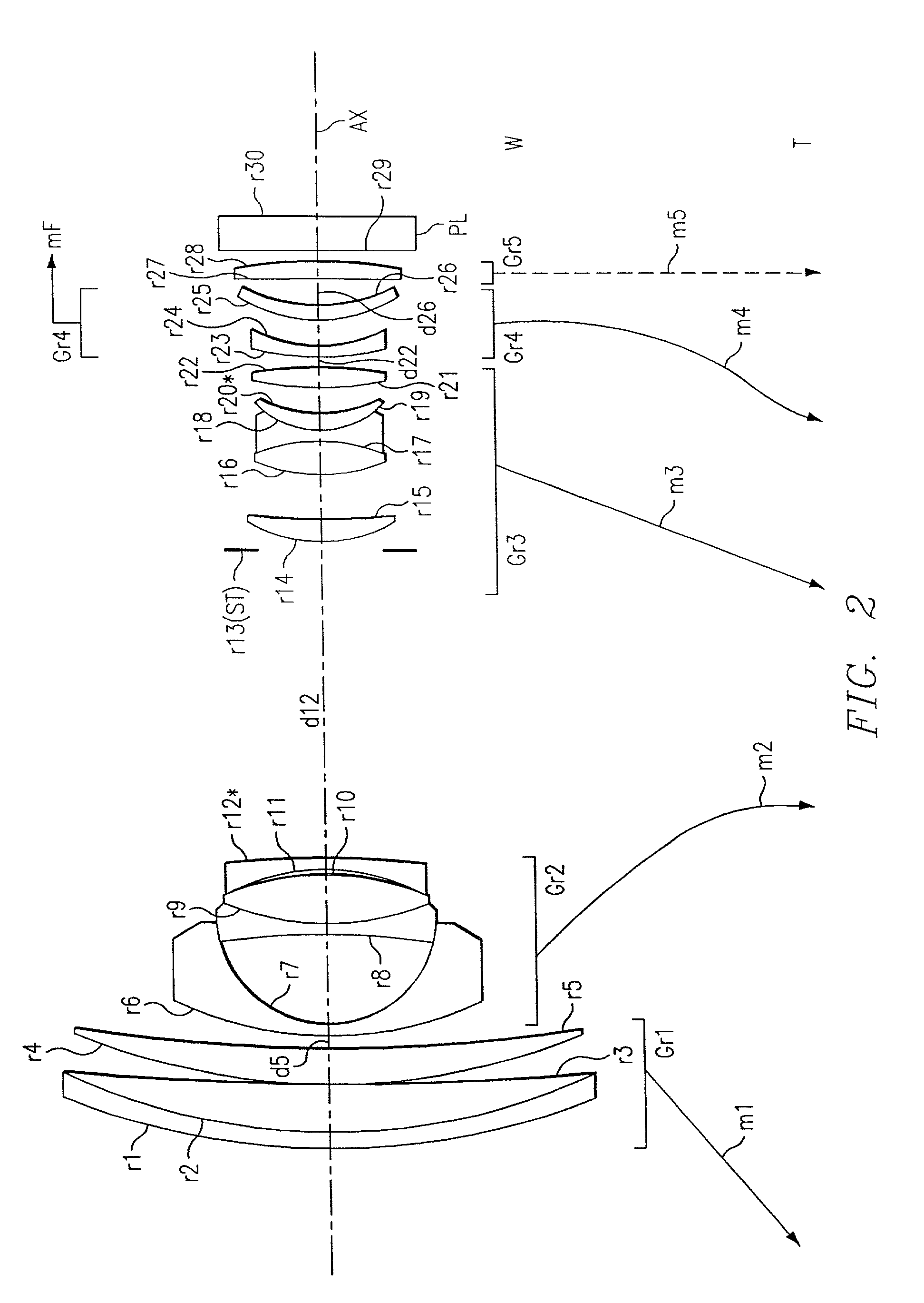
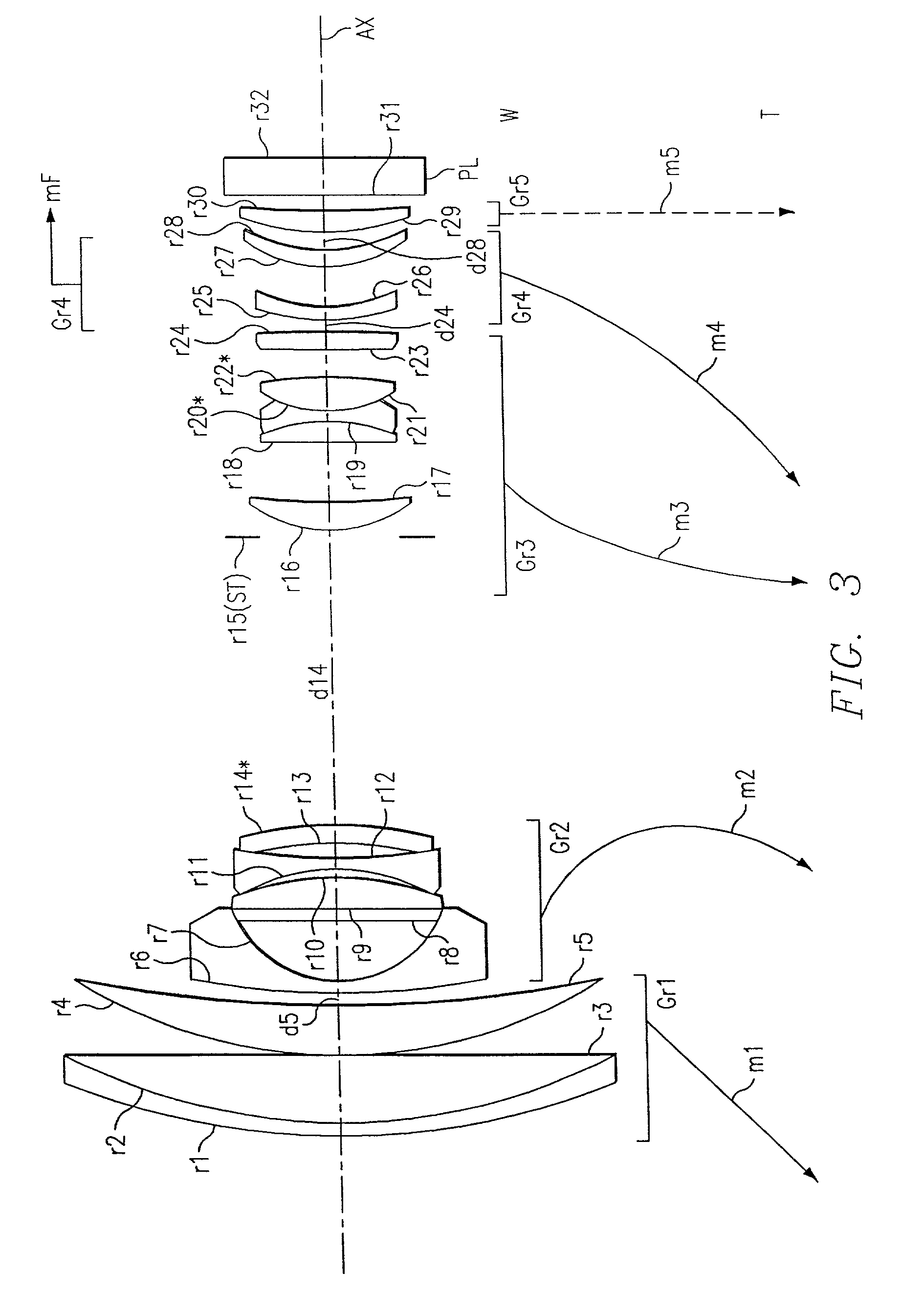
presented below correspond to the first embodiment to the ninth embodiment, respectively, as described hereinbefore, and the lens arrangement diagrams (FIGS. 1 to 9) showing the lens arrangement of the first to ninth embodiments apply also to Examples 1 to 9, respectively.

[0081] Tables 1 to 9 list the construction data of Examples 1 to 9, respectively. In the construction data of each example, ri (i=1, 2, 3, . . . ) represents the radius of curvature (mm) of the i-th surface from the object side, di (i=1, 2, 3, . . . ) represents the i-th axial distance (mm) from the object side, and Ni (i=1, 2, 3, . . . ) and .nu.i (i=1, 2, 3, . . . ) represent the refractive index Nd for the d-line and the Abbe number (.nu.d) of the i-th optical element from the object side, respectively. Moreover, in the construction data, for each of those axial distances that vary with zooming (i.e., variable aerial distances), three values are given that are, from left, the axial distance at the wide-angle end...


PUM


Abstract

A taking lens device has a zoom lens system that is comprised of a plurality of lens units and that achieves zooming by varying the unit-to-unit distances and an image sensor that converts an optical image formed by the zoom lens system into an electric signal. The zoom lens system is comprised of, from the object side, a first lens unit having a positive optical power, a second lens unit having a negative optical power, a third lens unit having a positive optical power, and a fourth lens unit having a negative optical power. The following conditional formula is fulfilled: 1.1<f1/fT<2.5, where f1 represents the focal length of the first lens unit, and fT represents the focal length of the entire optical system at the telephoto end.

Description

[0001] This application is based on Japanese Patent Applications Nos. 2000-111927 and 2000-368339, filed on Apr. 7, 2000 and Dec. 4, 2000, respectively, the contents of which are hereby incorporated by reference.[0002] The present invention relates to an optical or taking lens device. More specifically, the present invention relates to an optical or taking lens device that optically takes in an image of a subject through an optical system and that then outputs the image as an electrical signal by means of an image sensor. For example, a taking lens device that is used as a main component of a digital still camera, a digital video camera, or a camera that is incorporated in, or externally fitted, to a device such as a digital video unit, a personal computer, a mobile computer, a portable telephone, or a personal digital assistant (PDA). The present invention relates particularly to an optical or taking lens device provided with a compact, high-zoom-ratio zoom lens system.DESCRIPTION ...

Claims


Application Information

Patent Timeline
Patent Type & Authority Applications(United States)
IPC IPC(8): G02B15/20G02B15/173
CPCG02B15/173G02B15/144105G02B15/145121G02B15/1461
Inventor HAGIMORI, HITOSHIKOHNO, TETSUOISONO, MASASHI
Owner MINOLTA CO LTD
Why Eureka
Try Eureka