Image processing method and system for interpolation of resolution

a processing method and resolution technology, applied in the field of image processing technique for interpolation of resolution, can solve the problems of image quality degrading, image quality degrading like the nearest neighbor method, and the edges of regions and/or objects in the image tend to blur

Inactive Publication Date: 2001-12-06
NEC CORP
View PDF7 Cites 27 Cited by
  • Summary
  • Abstract
  • Description
  • Claims
  • Application Information

AI Technical Summary

Problems solved by technology

However, this method has a disadvantage that the image quality degrades due to jaggies formed at the boundaries or contours of the regions and / or objects.
However, the image quality degrades like the nearest neighbor method, because the edges of the regions and / or objects in the image tend to blur due to the use of the weighted average values.
However, the interpolation function used in this method serves basically as a low-pass filter and as a result, there is a disadvantage that the edges of the regions and / or objects in the image tend to blur if the objects include characters or letters.
However, the image enlargement device shown in FIG. 1 has the following problems:
Although blurs for the oblique edges are improved, blurs for the horizontal and vertical edges are scarcely improved, which are approximately the same as those generated by the cubic convolution method.
Also, almost no improvement is seen for thin lines having a width of one pixel.
Moreover, the device configuration is not suitable to real-time processing and thus, the device is difficult to be mounted on an image processing apparatus or system.

Method used


Image

  • Image processing method and system for interpolation of resolution
  • Image processing method and system for interpolation of resolution
  • Image processing method and system for interpolation of resolution

Examples


first embodiment

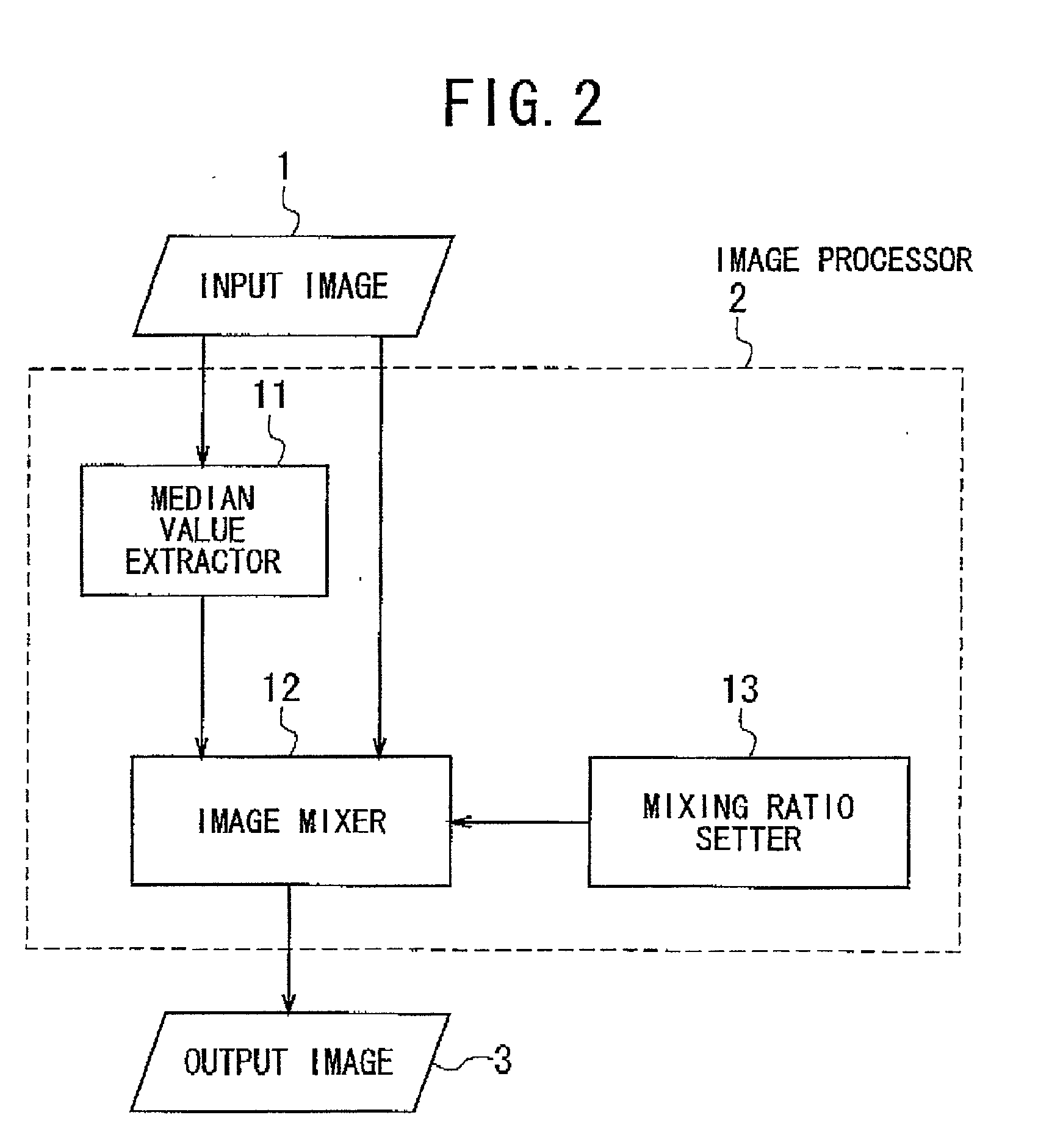
[0105] Specifically, as shown in FIG. 2, the image processing system of the first embodiment comprises an image processor 2 for processing an input image 1 and for outputting the processed image as an output image 3 The image processor 2 comprises a median value extractor 11, an image mixer 12, and a mixing ratio setter 13.

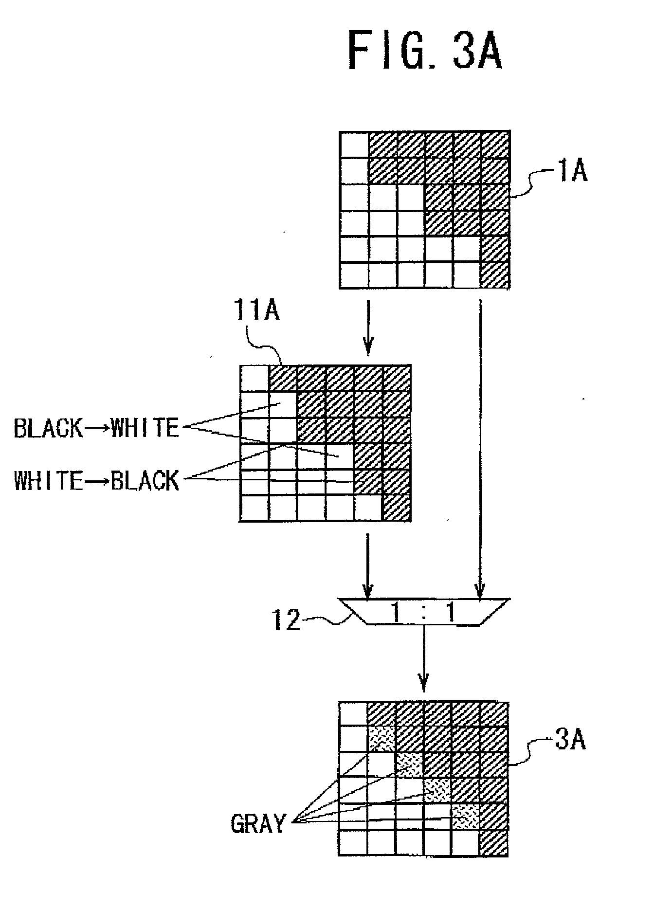
[0106] The median value extractor 11 provides a filtering operation that outputs the median value of the density or gray-scale levels of all the pixels (i.e., the pixel values) in a local area surrounding a target pixel of the input image 1. The median value is defined as a value in the middle of a series of the pixel values arranged in order of magnitude.

[0107] The image mixer 12 mixes the image subjected to the filtering operation in the extractor 11 (i.e., the filtered image) and the input image 1 itself at a mixing ratio specified by the mixing ratio setter 13, generating a mixed image. The mixing operation of the mixer 12 is performed by pixel by pixel in who...

second embodiment

[0125] Although the median value extractor 11 that uses the median filter is provided in the image processing system according to the first embodiment of the invention to change the phase of the jaggy in the input image in the invention is not limited to the use of the median filter. Any other filter that provides approximately the same function as the median filter may be used.

[0126] FIG. 4 shows an image processing system according to a second embodiment of the invention, which is used to carry out an image processing method according to the second embodiment.

[0127] The image processing system of the second embodiment comprises an image processor 2A for processing an input image 1 and for outputting the processed image as an output image 3. The image processor 2A comprises an average value calculator 14, a nearest value extractor 15, an image mixer 12, and a mixing ratio setter 13.

[0128] The average value calculator 14 calculates the average value of the density or gray-scale leve...

third embodiment

[0134] FIG. 5 shows an image processing system according to a third embodiment of the invention, which is used to carry out an image processing method according to the third embodiment.

[0135] The image processing system of the third embodiment comprises an image processor 2B for processing an input image 1 and for outputting the processed image as an output image 3 and an interpolation processor 5 for enlarging an original image 4 at a specific enlarging ratio through an interpolation process. The processor 5 is located outside the image processor 2B.

[0136] The output of the interpolation processor 5 is used as the input image for the image processor 2, which is unlike the first and second embodiments explained above.

[0137] The image processor 2B comprises a filter 16, an image mixer 12, and a mixing ratio setter 13

[0138] The filter 16 provides a filtering operation that has been explained in the first or second embodiment for the input image 1. The filter 16 may provide other filte...


PUM


Abstract

An image processing method is provided, which makes it possible to enlarge an input or original image in such a way as to suppress or eliminate jaggies at the contours in the image, and which is applicable to a dot-matrix type display device with a fixed resolution. In the step (a) a local area is defined in an input image. The local area includes a target pixel and neighboring pixels surrounding the target pixel. In the step (b), a filtering operation is applied to the target pixel and the neighboring pixels in the local area while all the pixels in the local area are successively assigned to the target pixel, thereby outputting a filtered image. In the step (c), the filtered image and the input image are mixed together at a specific mixing ratio, thereby forming an output image. In the step (b), the median or average value is preferably used for forming the filtered image.

Description

[0001] 1. Field of the Invention[0002] The present invention relates to an image processing technique for interpolation of resolution to enlarge input or original images, more particularly, the invention relates to an image processing method and an image processing system applicable to display controllers for various information processing systems, such as Liquid-Crystal Displays (LCDs), Electroluminescent (EL) displays, and Plasma Display Panels (PDPs); and a computer program product having a computer readable medium and a computer program recorded thereon that performs the method[0003] 2. Description of the Related Art[0004] Conventionally, image data sent from computers and graphic or video data for ordinary Televisions (TVs) according to the NTSC (National Television System Standard Committee) system or for High-Definition TVs (HDTVs) have various resolutions. The available resolutions of these data are specified by their formats.[0005] When images with different resolutions are...

Claims


Application Information

Patent Timeline
Patent Type & Authority Applications(United States)
IPC IPC(8): G06T3/40H04N1/387H04N1/409G06T5/20
CPCG06T3/403G09G2340/0407
Inventor SASAKI, DAIGO
Owner NEC CORP
Why Eureka
Try Eureka