
Disk input/output control device maintaining write data in multiple cache memory modules and method and medium thereof

Inactive Publication Date: 2001-12-06
FUJITSU LTD
View PDF0 Cites 18 Cited by
  • Summary
  • Abstract
  • Description
  • Claims
  • Application Information

AI Technical Summary

Benefits of technology

[0086] As described above, the present invention includes at least three cache memory modules and duplicates and saves write data while circulating the write data among the three cache memory modules. When there is a problem in the cache memory, the write data that was to be written to a region that was controlled by the cache memory module in which the problem occurred splits the data up among the remaining cache memory modules. This makes it possible to increase cache memory modules in units of one and allows more effective use of cache memory than the conventional hot pair system.[0087] The many features and advantages of the invention are apparent from the detailed specification and, thus, it is intended by the appended claims to cover all such features and advantages of the invention which fall within the true spirit and scope of the invention. Further, since numerous modifications and changes will readily occur to those skilled in the art, it is not desired to limit the invention to the exact construction and operation illustrated and described, and accordingly all suitable modifications and equivalents may be resorted to, falling within the scope of the invention.[0088] Element Number List[0089] 1-1.about.1-n Cache Memory[0090] 2 Disk Devices[0091] 3 Cache control modules[0092] 11 Server[0093] 12 RAID Control Device[0094] 12a Interface Control Module[0095] 12b Configuration Information Management Module[0096] 12c Cache Control Module[0097] 12d Cache Memory[0098] 12eDisk Control Module[0099] 12f Disk Device[0100] 12g Logical Volume[0101] 100 Hot spare system[0102] 101 Subsystem Control Module[0103] 101a Memory[0104] 101b MPU[0105] 101c Bus I / F (interface) Module[0106] 102 Cache 1[0107] 103 Device Control Module[0108] 103a Buffer[0109] 103b MPU[0110] 103c Memory[0111] 103d Bus I / F (interface) control module[0112] 104 Device I / F (interface) Module[0113] 105 Disk Drive Group[0114] 106 Cache X[0115] 107 Cache 2[0116] 108 Pair[0117] 110 Cache 3[0118] 112 Cache 4[0119] 116 Upper Device[0120] 118 Channel I / F (interface) Module[0121] 120 Bus[0122] 200 RAID control device[0123] 202 Configuration information[0124] 300 Computer system 400 Computer system

Problems solved by technology

However, the aforementioned conventional methods have the following disadvantages:

Method used


Image

  • Disk input/output control device maintaining write data in multiple cache memory modules and method and medium thereof
  • Disk input/output control device maintaining write data in multiple cache memory modules and method and medium thereof
  • Disk input/output control device maintaining write data in multiple cache memory modules and method and medium thereof

Examples


Embodiment Construction

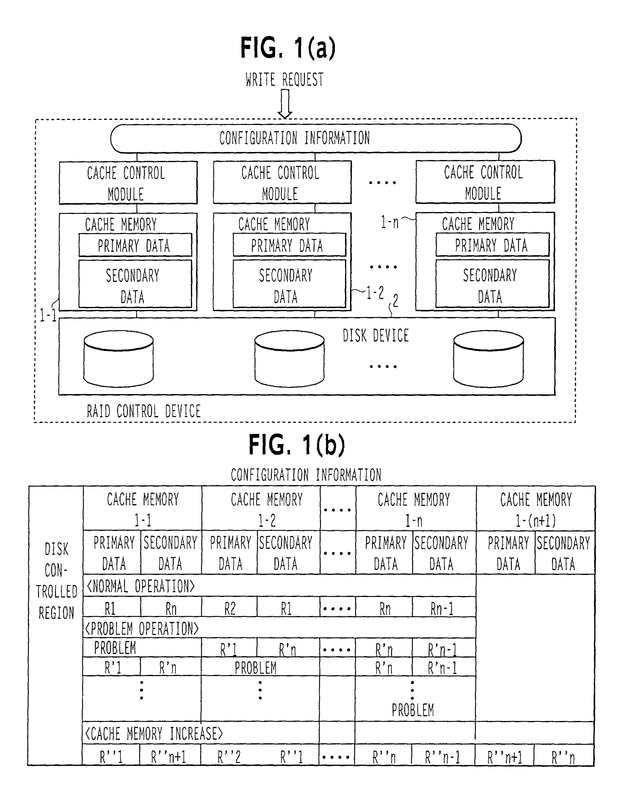
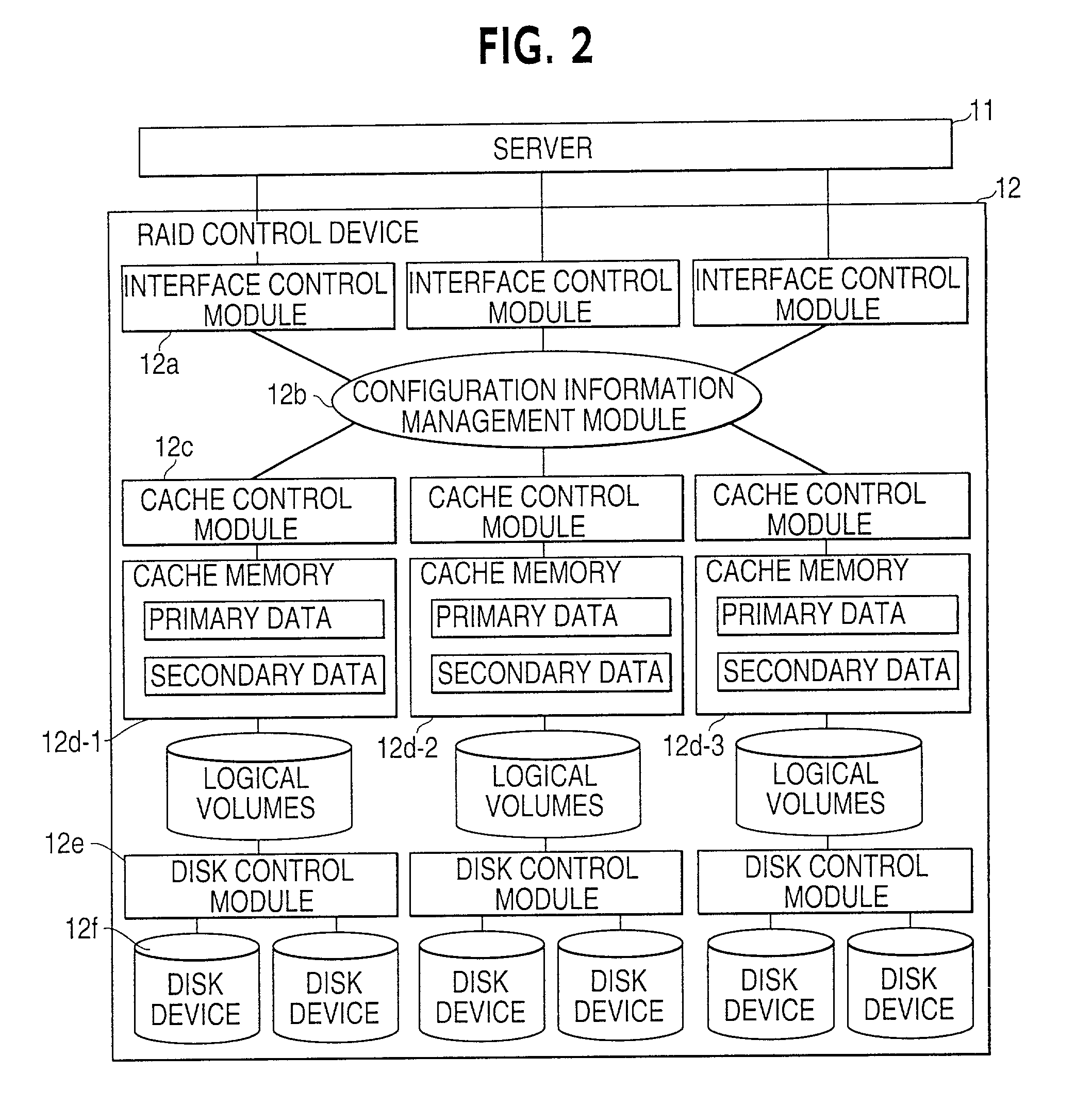
[0041] FIG. 2 is a diagram of a computer system 300 of an embodiment of the present invention. As shown in FIG. 2, computer system 300 comprises server 11 and RAID control device 12. RAID control device 12 corresponds to RAID control device 200 shown in FIG. 1(a).

[0042] Server 11 transmits a write request to RAID control device 12 to write data from the server 11 to logical volumes 12g allocated among disk devices 12f by disk control module 12e.

[0043] As described above with respect to the RAID control device 200 shown in FIG. 1(a), when the write request is received from the server 11 to write data from the server 11 to the disk devices 12f, a write request complete response is returned to the server 11 upon writing the data to the cache memory 12d. The write data stored in the cache memory 12d is written out to the disk devices 12f asynchronously to the write complete response (write back operation).

[0044] The RAID control device 12 also comprises interface control module 12a, con...


PUM


Abstract

An input / output control device uses all of its cache memory effectively and allows cache memory modules to be added in increments of one. When cache memory included in the input / output control device is operating normally and the input / output control device receives a write request from a processing device, the input / output control device returns a write request completed response after writing data to cache memory as set forth in configuration information included in the input / output control device. The write data in the cache memory is then written to one or more disk devices asynchronously with the write completed response. When there is a problem with a cache memory module, the write data that was to be written to the region controlled by the cache memory module where the problem occurred is divided among the remaining cache memory modules. When adding more cache memory modules, the input / output control device writes data to the cache memory in response to a write request from a processing device based on the configuration information after the cache memory was increased and after the data was moved as set forth in the configuration information corresponding to the cache memory increase.

Description

[0001] 1. Field of the Invention[0002] The present invention relates to an input / output control device for disks, and, more particularly, to an input / output control device that maintains write data in multiple cache memory modules.[0003] 2. Description of the Related Art[0004] RAID control devices typically include cache memory. In response to a write request received from a server, the RAID control devices return a write request complete response to the server just by writing the data to the cache memory. The write data stored in the cache memory is written to disk devices asynchronously to the write complete response sent to the server. This type of operation is called a write back operation. The response time of a disk device that uses a cache memory to perform a write back operation in response to a write request is many times (approximately 10 times) shorter than disk devices that have no cache memory.[0005] In order to guarantee permanence of the write data, RAID control devic...

Claims


Application Information

Patent Timeline
Patent Type & Authority Applications(United States)
IPC IPC(8): G06F3/06G06F12/08G06F12/16G06F13/00
CPCG06F11/1666G06F11/20G06F12/0868G06F2212/283
Inventor KATO, TADAOMIOMURA, HIDEAKIKUBOTA, HIROMI
Owner FUJITSU LTD
Learn More