Heating apparatus and method

Inactive Publication Date: 2001-12-20
CANON KK
View PDF0 Cites 11 Cited by
  • Summary
  • Abstract
  • Description
  • Claims
  • Application Information

AI Technical Summary

Benefits of technology

0023] The present invention has been made in view of the problems described above, and has as its object to provide a heating apparatus that can realize a large area in order to improve the thermal processing precision of the object to be heated without increasing the weight and heat capacity per unit area of the heating plate.
0024] It is another object of the present invention to provide a heating apparatus and method in which unwanted thermal deformation of the object to be heat

Problems solved by technology

As for the hole depth, increasing the depth while maintaining the same diameter as that of the prior art is technically difficult, and highly precise hole formation is limited in depth.
If the hole diameter is increased, while the processability increases and a deep hole can be formed easily, the plate thickness increases and the weight and heat capacity increase, leading to an increase in power consumption and heating and cooling times. For the heater, a length with which the heater can be fabricated with good precision for a certain diameter is limited.
In other words, an issue of realizing a large plate area without increasing the hea

Method used


Image

  • Heating apparatus and method
  • Heating apparatus and method
  • Heating apparatus and method

Examples


first embodiment

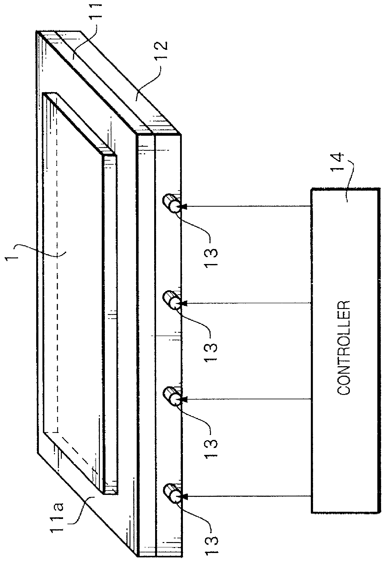
[0074] FIG. 1 is a view explaining a heating apparatus according to the present invention.

[0075] The heating apparatus of this embodiment is formed by stacking a base plate 11 on a heat transfer plate 12 in which rod heaters 13 controlled by a controller 14 are inserted, and heats an object 1 to be heated placed on the base plate 11.

[0076] The base plate 11 is made of stainless steel or the like having smaller creep than the heat transfer plate 12. The base plate 11 is fixed with a support member (not shown). The heat transfer plate 12 is made of aluminum or the like having a larger thermal conductivity than the base plate 11. The heat value of the rod heaters 13 is controlled by the controller 14 on the basis of a signal from at least one temperature sensor (not shown) placed on the base plate 11 or heat transfer plate 12. The object 1 to be heated is placed on a heating surface 11a of the base plate.

[0077] The heat transfer process from the rod heaters 13 to the object 1 to be hea...

second embodiment

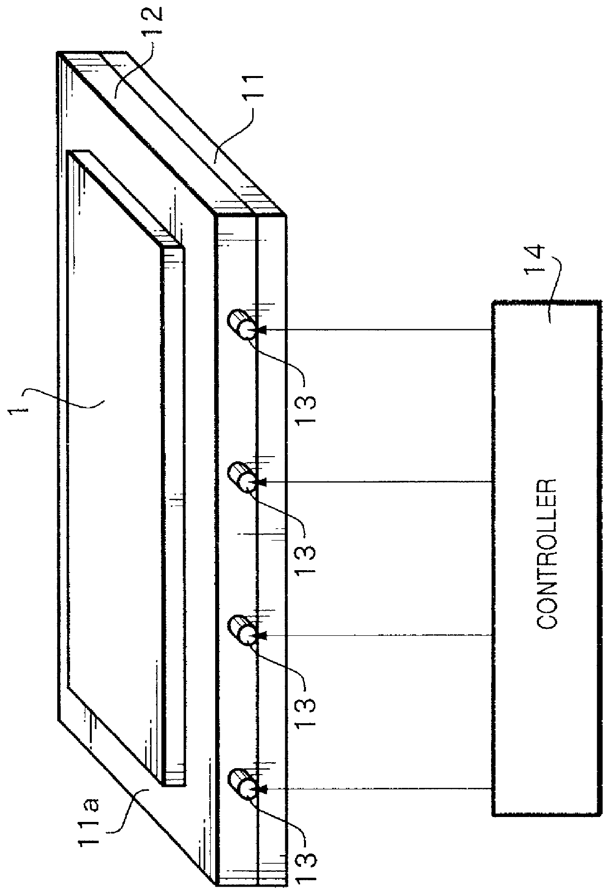
[0083] FIG. 2 is a view explaining a heating apparatus according to the present invention.

[0084] In the second embodiment, a heat transfer plate 12 in which rod heaters 13 are inserted directly heats an object 1 to be heated, and a base plate 11 is placed on the lower surface of the heat transfer plate 12, as shown in FIG. 2, i.e., the base plate 11 and heat transfer plate 12 are stacked in the reverse order. The second embodiment is different from the first embodiment described above in this respect.

[0085] Other than that, the second embodiment is similar to the first embodiment in, e.g., the materials of the base plate 11 and heat transfer plate 12, the fact that the heat value of the rod heaters 13 is controlled by a controller 14 on the basis of a signal from at least one temperature sensor (not shown) provided to the base plate 11 or heat transfer plate 12, and the like.

[0086] The heat transfer process from the rod heaters 13 to the object 1 to be heated in this embodiment will...

fourth embodiment

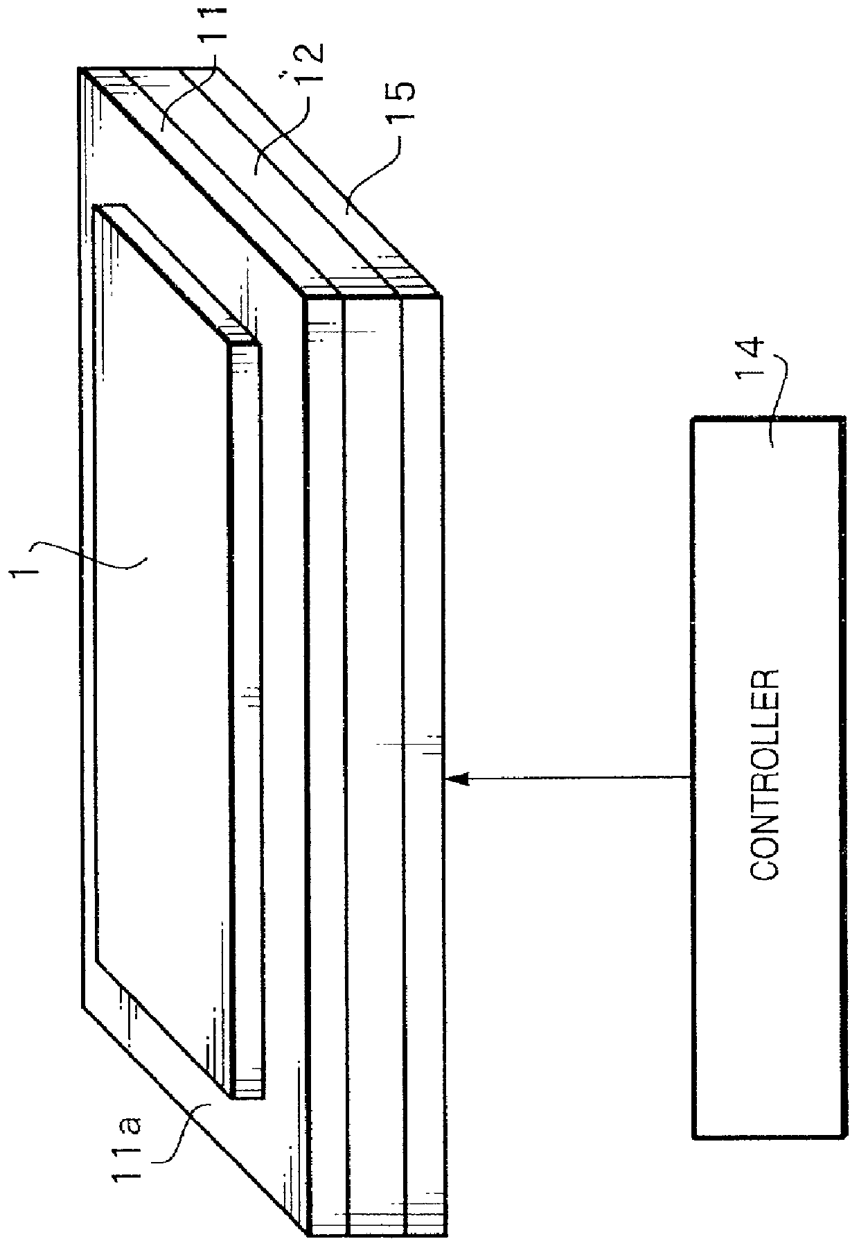
[0094] FIG. 4 is a view explaining a heating apparatus according to the present invention.

[0095] In the fourth embodiment, an auxiliary plate 16 is placed on the lower surface of a heat transfer plate 12. The fourth embodiment is different from the first embodiment in this respect. The auxiliary plate 16 is made of a material having a thermal conductivity and creep closer to those of a base plate 11 than those of the heat transfer plate 12. The auxiliary plate 16 may be made of the same material as that of the base plate 11.

[0096] Other than that, the fourth embodiment is similar to the first embodiment in, e.g., the materials of the base plate 11 and heat transfer plate 12, the fact that the heat value of rod heaters 13 is controlled by a controller 14 on the basis of a signal from at least one temperature sensor (not shown) provided to the base plate 11 or heat transfer plate 12, and the like.

[0097] In the fourth embodiment, in addition to the effect of the first embodiment, even ...


PUM

PropertyMeasurementUnit
Temperatureaaaaaaaaaa
Thicknessaaaaaaaaaa
Melting pointaaaaaaaaaa

Abstract

When an object to be heated is heated without temperature nonuniformity in its heated surface, unwanted thermal deformation can be suppressed, and thermal processing precision can be improved. For this purpose, a heat transfer plate for heating a plate-like object to be heated, and a base plate are stacked. A rod heater as a heat source is inserted in the heat transfer plate. The heat transfer plate has a larger thermal conductivity and smaller creep than the base plate.

Description

BACKGROUND OF THE INVENTION[0001] The present invention relates to a heating apparatus and method and, more particularly, to a technique for supporting an object to be heated such as a glass plate and subjecting it to a uniform temperature process in order to uniformly heat it.[0002] Conventionally, in a heating apparatus for uniformly heating an object to be heated, as shown in FIG. 37, a plurality of cartridge type rod heaters 213 are inserted in a plate 212 made of one material. Outputs from the rod heaters 213 are controlled by a controller 214 by referring to a temperature obtained by at least one temperature sensor (not shown) provided to the plate 212, thereby heating an object 1 to be heated. To decrease in-plane temperature nonuniformity of a heating surface 212a of the plate 212, a material such as an aluminum alloy having a large thermal conductivity is used. To prevent deformation of the plate 212, a material such as stainless steel having a small thermal conductivity an...

Claims


Application Information

Patent Timeline
IPC IPC(8): H05B3/20C03B29/02H01J9/26
CPCC03B29/025
Inventor KAMATA, SHIGETO
Owner CANON KK
Why Eureka
Try Eureka