Hydrocarbon reservoir testing

a hydrocarbon reservoir and well-testing technology, applied in the field of well-testing hydrocarbon reservoirs, can solve the problems of major drawbacks and general compromise of overall analysis, and achieve the effect of less engineer time requirements and more accurate simulation

Inactive Publication Date: 2001-12-27
KEPLER RES & DEV
View PDF0 Cites 29 Cited by
  • Summary
  • Abstract
  • Description
  • Claims
  • Application Information

AI Technical Summary

Benefits of technology

0008] The invention is therefore directed towards addressing this problem...

Problems solved by technology

While this method is quite sound in its reasoning, it suffers from a major drawback.
This is an inaccuracy which arises because of use of crude representation...

Method used


Image

  • Hydrocarbon reservoir testing
  • Hydrocarbon reservoir testing
  • Hydrocarbon reservoir testing

Examples


Embodiment Construction

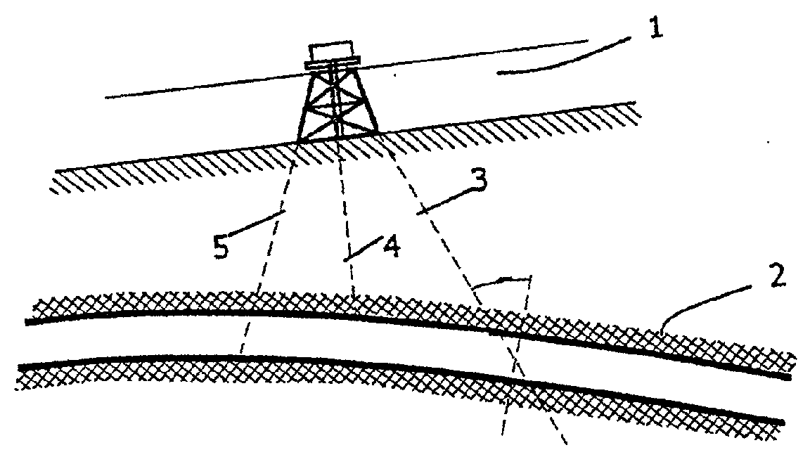
[0045] Referring to FIG. 1, the overall context for reservoir testing is illustrated. A testing rig 1 is erected over a payrock 2 containing a reservoir of a hydrocarbon (oil or gas). A wellbore 3 is drilled at an angle into the payrock, and alternative angles 4 and 5 are shown.

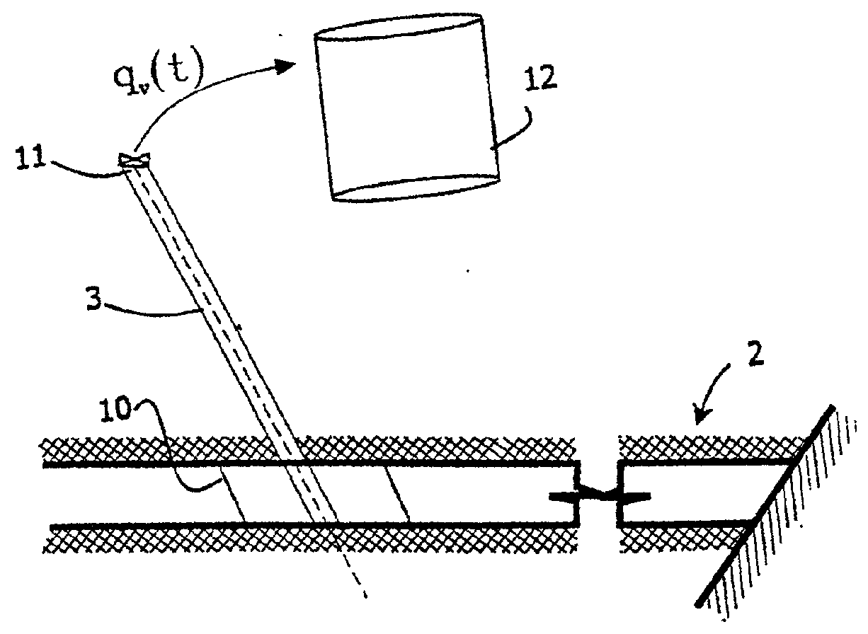
[0046] As shown in FIG. 2, the part of the payrock 2 surrounding the wellbore 3 is referred to as a damaged zone 10. Oil flows through the damaged zone 10 and the lining perforations into the wellbore 3 under the reservoir pressure. A valve 11 controls flow from the top of the wellbore 3 to a stock tank 12. A fault line 13 at one end of the payrock 2 is also illustrated in this diagram. Flow from the wellbore 3 to the stock tank 12 is denoted q.sub.v(t) and wellbore storage is denoted cV.sub.st. Various pressure sensors (not shown) are mounted within the wellbore 3 so that an actual pressure change (or curve) as a function of time can be measured.

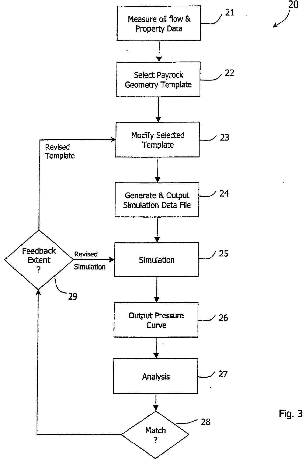
[0047] Referring now to FIGS. 3, 4(a), and 4(b) a method 20 for...


PUM


Abstract

A reservoir in a payrock (2) is analyzed using finite element simulation. A reservoir engineer selects an appropriate model from a set of template models, each comprising a set of polygons (51) in plan and layers (53) in elevation. The polygons are defined in objects instantiated from classes by control points and the layers as depth values of control points. A pattern object sweeps rotationally about a wellbore in a wellbore polygon to define a pattern of elements, fewer in number with distance from the wellbore. A polygon object also sweeps linearly from a generator line in the direction of a base line. The generator and a base lines correspond to polygon boundaries. Finite element simulation is performed with the model so derived.

Description

[0001] 1. Field of the Invention[0002] The invention relates to well testing of hydrocarbon reservoirs to determine economic viability.[0003] The purpose of reservoir simulation is to determine as precisely as possible the extent (volume), nature, permeability, and porosity of the payrock.[0004] 2. Prior Art Discussion[0005] In well testing a wellbore is drilled into the payrock, usually at an angle to vertical. The wellbore is lined and the lining is perforated at locations within the payrock. Oil or gas in the payrock flows into the wellbore through these perforations and the pressure arising from his flow is measured by pressure gauges within the wellbore. Flow of oil or gas from the wellbore opening is controlled by pumps and valves at the opening.[0006] For simulation, the hydrocarbon stock which flows from the wellbore is analysed and parameters such as the compressibility and the viscosity are determined. Also, geological surveys are performed. The combined information so gat...

Claims


Application Information

Patent Timeline
IPC IPC(8): E21B49/00G01V9/00G06T17/20
CPCE21B49/00
Inventor ROBINSON, JAMESCAMPBELL, JOHN
Owner KEPLER RES & DEV
Why Eureka
Try Eureka