Core for injection molding tools

a technology of injection molding tools and cores, which is applied in the direction of manufacturing tools, applications, welding apparatuses, etc., can solve the problems of low cost, elongated cores, and inability of cavity portions of molds to meet the needs of injection molding, and achieve high thermal conductivity materials

Inactive Publication Date: 2002-01-10
CHECK JOHN M +1
View PDF0 Cites 17 Cited by
  • Summary
  • Abstract
  • Description
  • Claims
  • Application Information

AI Technical Summary

Benefits of technology

0011] In one embodiment a core is provided as a solid metal tip of high thermal conductivity material. In another embodiment a core is configured to have a shaped inner wall suitable for forming a preform for a non-round plastic bottle.

Problems solved by technology

One problem with such arrangements is that molded parts having an elongated configuration must be formed, in part, by a core that has a length to width ratio large enough to allow the core to deflect when impacted by material that is injected against the core under high pressure conditions.
Since many materials are best shaped and densified under such high-pressure conditions, one problem with prior art apparatus is how to provide a low cost, elongated core that will not deflect or warp under high temperature and high-pressure operation.
Another problem with such molding apparatus is that the coolant flow is restricted to an annular surface in such a way as to limit the removal of heat from each of the mold cavities.
In addition, while the temperature of the core can be controlled using the fluid cooling system, the cavity portion of the mold cannot.

Method used


Image

  • Core for injection molding tools
  • Core for injection molding tools
  • Core for injection molding tools

Examples


Embodiment Construction

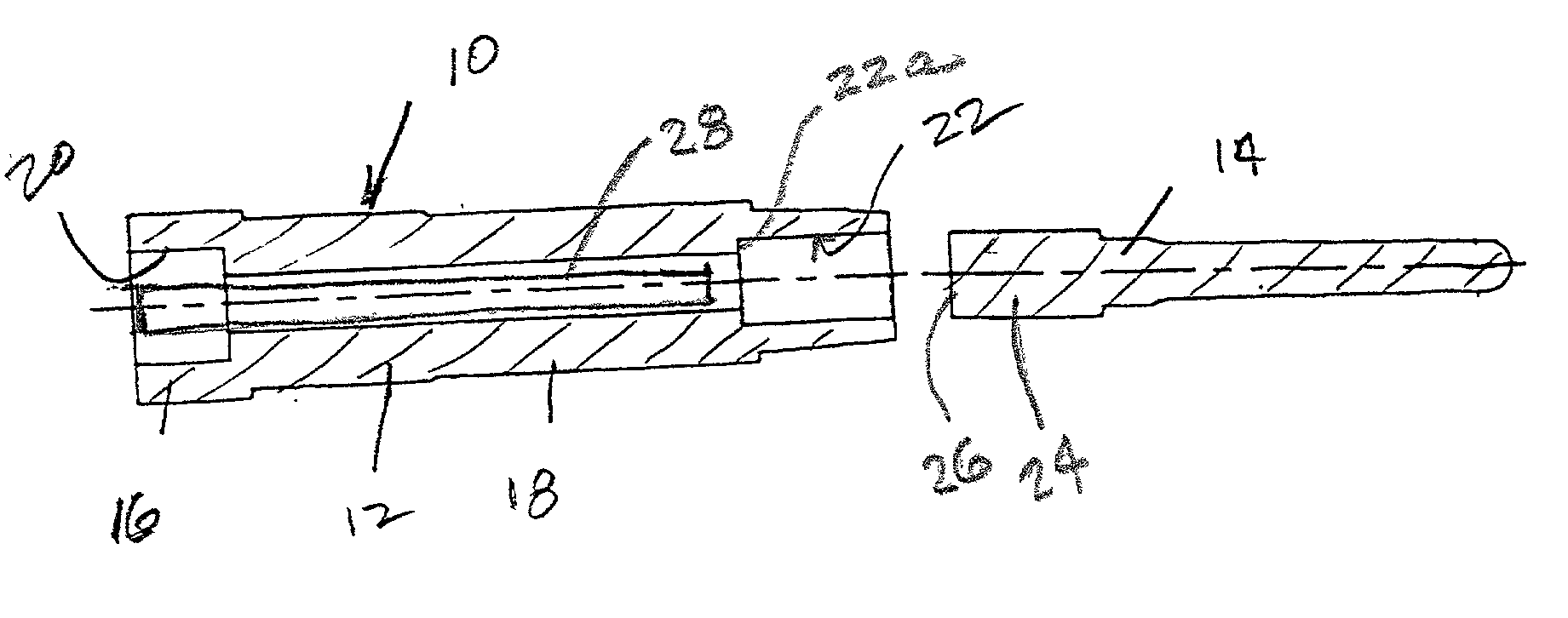
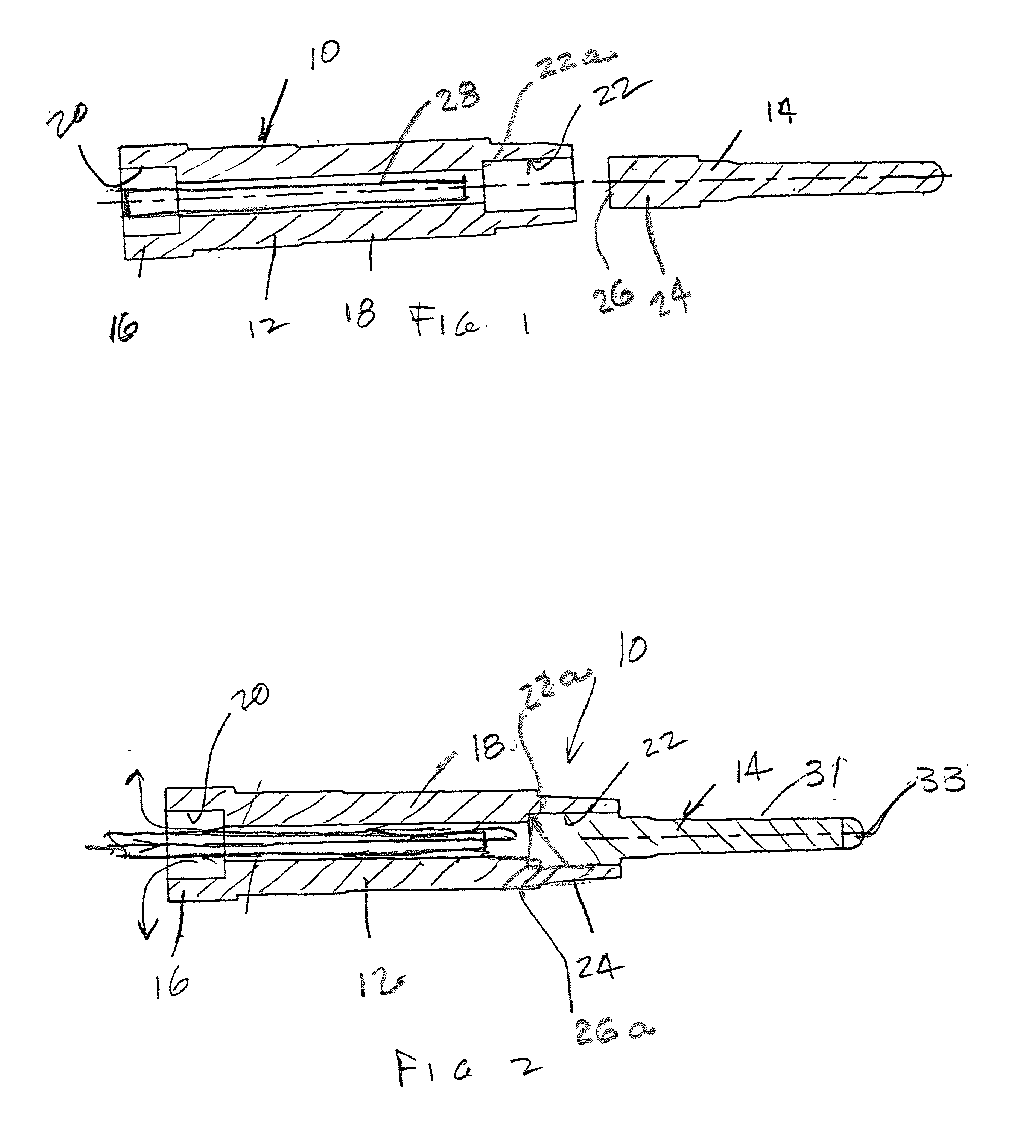
[0018] An integral bubbler type water-cooled core element or core assembly 10 is shown in FIG. 1 as having a core support member 12, and a core part 14. The support member 12 is configured to be supported within a known mold apparatus of the type shown in U.S. Pat. No. 5,498,150 issued to me on Mar. 12, 1996. Such apparatus includes separable mold parts one of which carries the core support member and includes cooling passages for connection to an inlet segment 16. An extension segment 18 locates the core 14 within a mold part cavity that will receive plastic or other material to be cooled by fluid flow through the interior of the member 12.

[0019] More particularly, the member 12 has a bore 20 at one end thereof adapted to be connected to a coolant source. The member 12 includes a bore 22 at the opposite end for supporting the core 14. The core 14 is configured as a solid metal piece of high heat conductivity material and includes a large diameter end 24 thereon with a flat planar e...


PUM

PropertyMeasurementUnit
strengthaaaaaaaaaa
thermal diffusivityaaaaaaaaaa
thermal conductivityaaaaaaaaaa

Abstract

A core for molding apparatus includes inner surface configurations for improving the cooling of injected plastic material.

Description

[0001] This is a utility application based upon provisional U.S. Application No. 60 / 169,165 filed Dec. 6, 2000.[0002] This invention relates to molding apparatus and more particularly to molding apparatus having water-cooled core and cavity assemblies that cooperate to form hollow molded parts. The apparatus is an improvement on the molding apparatus shown in U.S. Pat. No. 5,498,150 issued to me on Mar. 12, 1996 and incorporated herein by reference.[0003] To decrease cycle time and to insure good molding of either metal casting or injection molded plastic parts, it is advantageous to provide coolant flow passages within a mold apparatus. When cooling fluid is passed through such passages during the molding process, it removes heat from the apparatus. Where a molding apparatus includes a mold cavity part that has a plurality of female cavities formed within it, and where those female cavities are configured to receive core parts that cooperate with the female cavities to form the sur...

Claims


Application Information

Patent Timeline
Patent Type & Authority Applications(United States)
IPC IPC(8): B29C45/73
CPCB29C45/73B29C45/7312B29K2105/253
Inventor CHECK, JOHN M.JACKSON, CLETIS
Owner CHECK JOHN M
Why Eureka
Try Eureka