Isotherm Cooking Plate Apparatus, System, and Method of Manufacture

a technology of isothermal cooking plate and cooking plate body, which is applied in the direction of ohmic-resistance heating, oven/grill, kitchen equipment, etc., can solve the problem that the estimated cost of each independently controllable and readily replaceable isothermal cooking plate assembly is less than $200, and achieves high thermal conductivity, high thermal conductivity material, and corrosion resistance.

Pending Publication Date: 2021-07-22
EGGERS & ASSOC LLC
View PDF3 Cites 3 Cited by
  • Summary
  • Abstract
  • Description
  • Claims
  • Application Information

AI Technical Summary

Benefits of technology

[0015]The uniformly thick first plate of high thermal conductivity material may optionally be roll bonded on top cooking surface of first plate with a cladding layer, for instance, formed of austenitic stainless steel, such as a Type 304 and having a thickness of 0.002 to 0.010 inch. The corrosion-resistant and durable cladding (e.g., austenitic stainless steel) may be applied by roll bonding, plasma spray coating or vapor deposition processes. In addition, the hardness, wear resistance, corrosion resistance, and lubricity of the exterior surface of the stainless steel cladding may be further improved using metal finishing processes such as MEDCOAT 2000™ provided by the Electrolyzing Corporation of Ohio (Cleveland, Ohio). Alternatively, the cooking surface of the first plate of high thermal conductivity material may coated with a corrosion resistant and durable surface layer applied by electroplating or electroless plating processes (e.g., nickel or chrome plated surface coating).
[0016]A non-stick coating may be advantageously disposed on and in good thermal communication with the top cooking surface of the first plate of high thermal conductivity material of the present disclosure to minimize the need for supplemental cooking liquids (e.g., cooking oils) and to minimize the effort required to clean adhered food residue from the top cooking surface following prior cooking processes. If a non-stick coating is disposed on and in good thermal communication with the top cooking surface of the first plate, its application and curing would occur only after all of the thick-film printing and firing steps for the first electrically insulative layer, second electrically resistive heating element, third electrically conductive bus strips, and optional fourth electrically insulative covering layer, as specified below.
[0035]The thickness of the first plate of high thermal conductivity material of the isothermal cooking plate assembly is optimized to [a] provide the thermal conductance required to maintain a substantially uniform temperature across the entire surface of the first plate in the presence of varying heat dissipation rates across the entire surface of the first plate while [b] minimizing the time required to heat up the first plate of the isothermal cooking plate assembly to the user-selected set-point temperature. The thermal conductance between the electrically resistive heating element and the first plate is selected to be sufficiently high to enable the first plate to be heated to the selected set-point temperature within several tens of seconds. By way of example, the first plate of the present disclosure can be heated from room temperature to 150 C within less than 30 seconds for resistive heating elements energized with a maximum applied alternating current of 20 amps at an applied line voltage of 115 volts.
[0039]The side of the first plate of high thermal conductivity material opposite the top cooking surface and containing the thick-film printed and fired heater circuit assembly may be thermally insulated to reduce unwanted heat loss from the side of the first plate that is opposite the top cooking surface. By way of example, a rigid second plate of low thermal conductivity material covers the entire surface of the first plate of high thermal conductivity material on the side opposite the top cooking surface. The second plate of low thermal conductivity material (i.e., thermally insulative material) may be selected from the family of plastic materials including, for example, polyphenylene sulfide, polyamide-imide, polyetherimide, and polyetheretherkeytone offering low thermal conductivity, durability, and capability to withstand continuous operation at temperatures of 200 C or greater. An air gap is introduced between the back side of the thermally conductive first plate on which the heater circuit assembly is disposed and the front side of the thermally insulative second plate in order to reduce heat losses from the back side of the first plate. By way of example, the thermally insulative second plate may be attached to the first plate using an intervening high-temperature gasket material around the perimeter (e.g., silicone gasket) to effect a small air gap (e.g., 0.1 to 0.2 inch) between the plates, thereby providing high thermal impedance and low heat loss from the heater side of the first plate due to the very low thermal conductivity of air. Alternatively, the front side of the thermally insulative second plate may be positioned opposite the back side of the thermally conductive first plate on which the heater circuit assembly is disposed with an air gap while not mechanically attached to the first plate.
[0042]providing one or more thick-film printed and fired first electrically insulative layers disposed on the side opposite the cooking surface of first plate, the total thickness of the one or more first electrically insulative layers, after firing, selected to be sufficiently small and the associated temperature gradient through the first electrically insulative layer is sufficiently small during the application of the maximum heat flux level during rapid heat-up to prevent fracture, cracking and / or breaking of the first electrically insulative layer during rapid heat-up of first plate to a set-point temperatures of at least 150 C;

Problems solved by technology

In addition, the estimated cost for each independently controllable and readily replaceable isothermal cooking plate assembly is less than $200.

Method used


Image

  • Isotherm Cooking Plate Apparatus, System, and Method of Manufacture
  • Isotherm Cooking Plate Apparatus, System, and Method of Manufacture
  • Isotherm Cooking Plate Apparatus, System, and Method of Manufacture

Examples


example 1

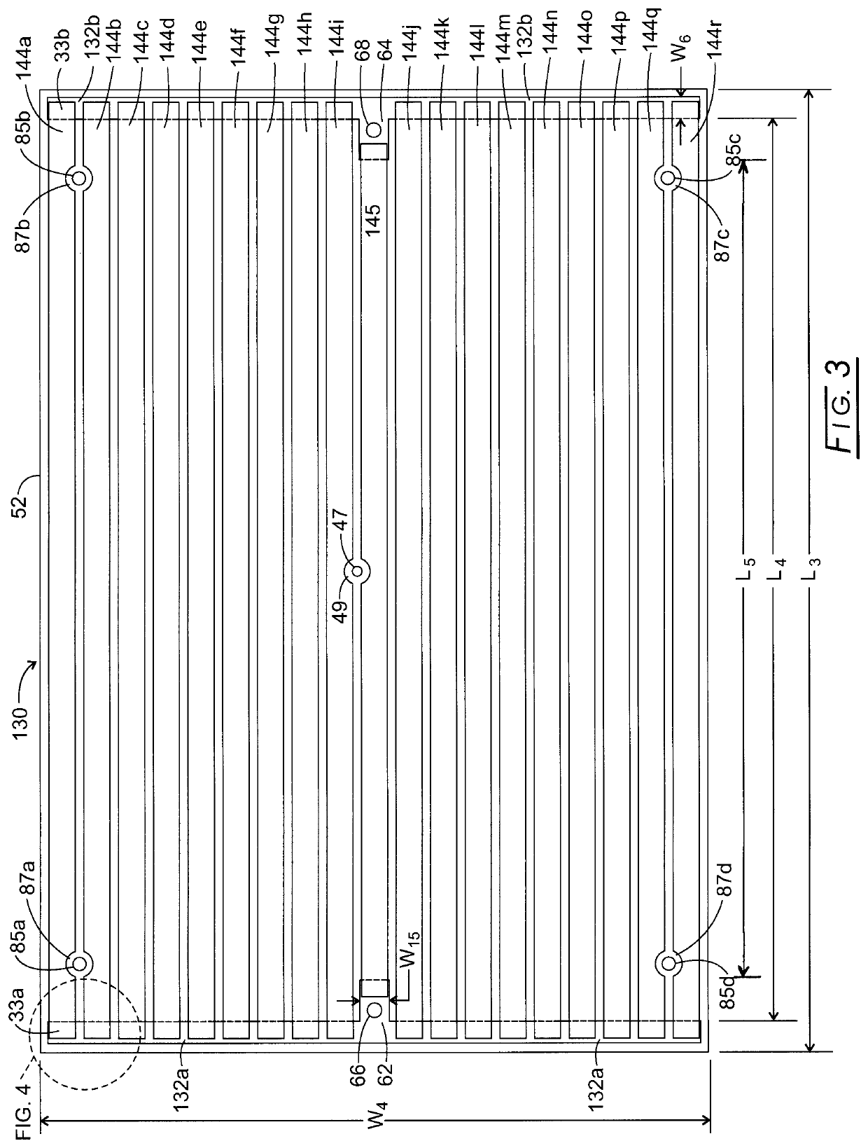
[0079]In this first example, as seen in Equation 1J, the maximum allowed thickness, tdielectric of the thick-film printed and fired first electrically insulative layer is determined based on the thermal conductivity, kdielectric of the thick-film printed and fired first electrically insulative layer and the maximum applied heat flux, {Qheater / Aheater} during the rapid heat-up of the first plate. By way of this first example, the overall dimensions of a first plate of an isothermal cooking plate assembly of a griddle system are 6.0 inches×9.0 inches. The total area of 19 thick-film printed and fired second electrically resistive heating element legs (as seen in FIG. 3) disposed on the thick-film printed and fired first electrically insulative layer that covers substantially the entire back surface of first plate is 48.0 square inches (309.6 sq. cm.). Due to the necessary spacing between second electrically resistive heating element legs, the total area of 19 thick-film printed and fi...

example 2

[0083]In this second example, as seen in Equation 1J, the maximum allowed thickness, tdielectric of the thick-film printed and fired first electrically insulative layer is determined by the thermal conductivity, kdielectric of the thick-film printed and fired first electrically insulative layer and the maximum applied heat flux, {Qheater / Aheater}. By way of this second example, the overall dimensions of a first plate of an isothermal cooking plate assembly of a griddle system are 6.0 inches×9.0 inches. The total area of 19 thick-film printed and fired second electrically resistive heating element legs (as seen in FIG. 3) disposed on the thick-film printed and fired first electrically insulative layer that covers substantially the entire back surface of first plate is 48.0 square inches (309.6 sq. cm.). Due to the necessary spacing between second electrically resistive heating element legs, the total area of 19 thick-film printed and fired second electrically resistive heating elemen...

example 3

[0088]In this third example, as seen in Equation 1J, the maximum allowed thickness, tdielectric of the thick-film printed and fired first electrically insulative layer is determined by the thermal conductivity, kdielectric of the thick-film printed and fired first electrically insulative layer and the maximum applied heat flux, {Qheater / Aheater}. By way of this third example, the overall dimensions of a first plate of an isothermal cooking plate assembly of a griddle system are 5.0 inches×6.0 inches. The total area of 19 thick-film printed and fired second electrically resistive heating element legs (as seen in FIG. 3) disposed on the thick-film printed and fired first electrically insulative layer that covers substantially the entire back surface of first plate is 24.0 square inches (154.8 sq. cm.). Due to the necessary spacing between second electrically resistive heating element legs, the total area of 19 thick-film printed and fired second electrically resistive heating element ...


PUM

PropertyMeasurementUnit
thicknessaaaaaaaaaa
surface areaaaaaaaaaaa
applied voltageaaaaaaaaaa

Abstract

An isothermal cooking plate assembly is formed from a first plate of high thermal conductivity material having a back surface and an oppositely disposed top cooking surface. One or more heater circuit assemblies are disposed on the first plate back surface for forming a composite having a back surface. A controller is in electrical connection with the heater circuit assemblies for controlling temperature of the first plate of high thermal conductivity material. The first plate can be Aluminum Type 1100 or Aluminum Type 6061. The first plate can be a laminate formed from a clad bottom metal layer and clad top cooking surface metal layer, where the clad layers formed from the same material and having about the same thickness. The clad material can be austenitic stainless steel. A second plate of low thermal conductivity material can be attached to the composite back surface of first plate.

Description

CROSS-REFERENCE TO RELATED APPLICATIONS[0001]This application is a continuation-in-part of application Ser. No. 16 / 044,774 filed Jul. 25, 2018 which in turn is a continuation-in-part of application Ser. No. 14 / 526,570 filed Oct. 29, 2014, which claims benefit of provisional application Ser. No. 61 / 899,415 filed on Nov. 4, 2013; the disclosures of which are expressly incorporated herein by reference.STATEMENT REGARDING FEDERALLY SPONSORED RESEARCH AND DEVELOPMENT[0002]Not applicable.THE NAMES OF THE PARTIES TO A JOINT RESEARCH AGREEMENT[0003]Not applicable.REFERENCE TO A “SEQUENCE LISTING,” A TABLE, OR A COMPUTER PROGRAM[0004]Not applicable.STATEMENT REGARDING PRIOR DISCLOSURES BY THE INVENTOR OR A JOINT INVENTOR[0005]Not applicable.BACKGROUND OF THE INVENTION[0006]The accurate temperature control of cooking plate assemblies, also known as griddles, is required for certain food processing wherein variable rates of heat dissipation exist across the extent of the cooking surface. Some ...

Claims


Application Information

Patent Timeline
Patent Type & Authority Applications(United States)
IPC IPC(8): H05B1/02A47J37/06H05B3/26H05B3/12
CPCH05B1/0266A47J37/0676H05B2213/07H05B3/12H05B2203/013H05B3/262H05B3/688Y10T29/49117
Inventor EGGERS, PHILIP E.
Owner EGGERS & ASSOC LLC
Why Eureka
Try Eureka