Fuel injector with bifurcated recirculation zone

a fuel injector and recirculation zone technology, which is applied in the ignition of turbine/propulsion engines, engine starters, lighting and heating apparatus, etc., can solve the problems of difficult to achieve the nox emission goal, difficult to control nox generation, and low nox production, so as to achieve low nox emissions, reduce nox emissions, and improve the effect of lean blowout performan

Inactive Publication Date: 2002-01-31
CROCKER DAVID S +2
View PDF0 Cites 80 Cited by
  • Summary
  • Abstract
  • Description
  • Claims
  • Application Information

AI Technical Summary

Benefits of technology

0021] Another object of the invention is the provision of fuel injectors for gas turbine engines which result in low emissions of pollutants, particularly low NOx emissions, and CO emissions at low power conditions such as idle.
0022] Another object of the present invention is the

Problems solved by technology

Advanced gas turbine combustors must meet these requirements for lower NOx emissions under conditions in which the control of NOx generation is very challenging.
The severe combustor pressure and temperature conditions req

Method used


Image

  • Fuel injector with bifurcated recirculation zone
  • Fuel injector with bifurcated recirculation zone
  • Fuel injector with bifurcated recirculation zone

Examples


Embodiment Construction

. 3

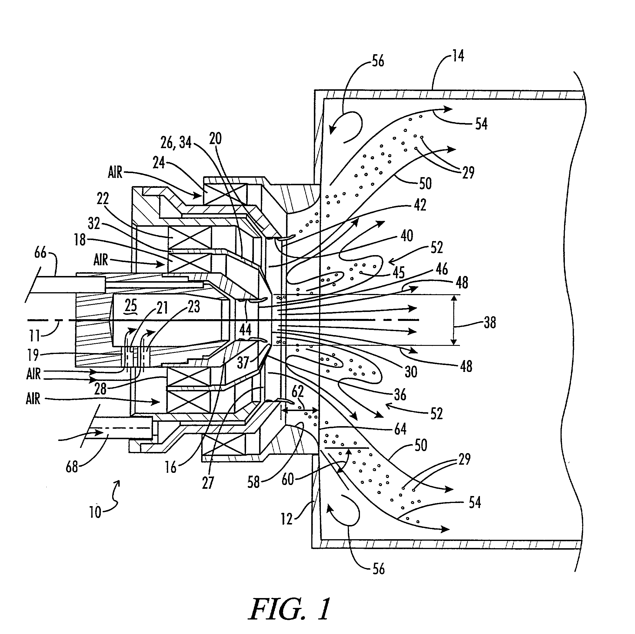
[0063] FIG. 3 illustrates a third embodiment of the fuel injection system of the present invention which is shown and generally designated by the numeral 200. The fuel injector system 200 is a simplex pressure atomizer piloted system similar to that of FIG. 2. The system 200 includes a simplex pressure atomizer pilot fuel injector 202, a pilot swirler 204, air splitter 206, an inner main swirler 208, and airblast main fuel injector 210, an outer main swirler 212, and a flared aft outlet wall 214. Differences as compared to the fuel injector system 100 of FIG. 2 include a slightly different geometry of the air splitter 206, and the use of an axial vaned outer main swirler 212 rather than the radial swirler of FIG. 2.

[0064] FIG. 3 also includes a schematic representation of the shape and color of both a pilot flame 216 and a main flame 218 at full power conditions and a 10 / 90 pilot / main fuel flow split. As previously noted, the pilot flame 216 is anchored by and generally contained...


PUM


Abstract

A gas turbine fuel injection system of the lean direct injector type designed to reduce nitrous oxide (NOx) emissions is provided. The configuration includes a pilot fuel injector for injecting a pilot fuel stream, and a pilot swirler for providing a swirling pilot air stream to atomize and entrain the pilot fuel stream. A main airblast fuel injector is located concentrically about the pilot fuel injector, for injecting a main fuel stream concentrically about the pilot fuel stream. Inner and outer main swirlers provide a swirling main air stream to atomize and entrain the main fuel stream. An air splitter is located between the pilot swirler and the main swirler. The air splitter is so arranged and constructed as to divide the pilot air stream exiting the pilot swirler and the air splitter, from the main air stream exiting the inner main swirler, whereby a bifurcated recirculation zone is created.

Description

REFERENCE TO PRIOR APPLICATIONS[0002] This application claims benefit of our co-pending provisional patent application Ser. No. 60 / 176,379 filed on or about Jan. 13, 2000 entitled "METHOD AND APPARATUS FOR DECREASING COMBUSTOR EMISSIONS".[0003] 1. Field of the Invention[0004] The present invention relates generally to fuel injection assemblies for gas turbine engines, and more particularly, but not by way of limitation, to fuel injectors of the general type known as lean direct injectors (LDI) which are designed to reduce nitrous oxide (NOx) emissions.[0005] 2. Description of the Prior Art[0006] There is a continuing need, driven by environmental concerns and governmental regulations, for improving the efficiency of and decreasing the emissions from gas turbine engines of the type utilized to power jet aircraft or generate electricity. Particularly, there is a continuing drive to reduce nitrous oxide (NOx) emissions.[0007] Advanced gas turbine combustors must meet these requirements...

Claims


Application Information

Patent Timeline
IPC IPC(8): F02C7/22F23D11/10F23R3/34
CPCF02C7/22F05D2270/082F23D11/107F23D2900/00015F23D2900/11101F23R3/343Y02T50/677Y02T50/60
Inventor CROCKER, DAVID S.NICKOLAUS, DANIEL A.SMITH, CLIFFORD E.
Owner CROCKER DAVID S
Why Eureka
Try Eureka