Method for operating a drive device and corresponding drive device

a drive device and drive device technology, applied in mechanical equipment, machines/engines, electric control, etc., can solve the problems of affecting the operation efficiency the time period that passes until the catalytic converter reaches the operating temperature, and the exhaust gas is not reliably or not completely purified, so as to achieve reliable heating of the catalytic converter and low pollutant emission

Active Publication Date: 2018-06-26
AUDI AG
View PDF28 Cites 0 Cited by
  • Summary
  • Abstract
  • Description
  • Claims
  • Application Information

AI Technical Summary

Benefits of technology

[0010]It is therefore an object of the invention to provide a method for operating a drive device that does not have the aforementioned disadvantages, but enables in particular in each operating state of the internal combustion engine a reliable heating of the catalytic converter by means of the heating device, while at the same time ensuring a low pollutant emission.

Problems solved by technology

In particular at low external temperatures and / or a cold start of the drive device, however, the time period that passes until the catalytic converter reaches the operating temperature, may be relatively long.
In this time period the reaction cannot occur or can only occur at low efficiency so that the exhaust gas is not reliably or not completely purified.
This problem is particularly pronounced in the hybrid drive device because in this case the internal combustion engine is not constantly in operation.
When the temperature falls below the operating temperature, the exhaust gas generated when reactivating the drive device or the internal combustion engine cannot reliably be purified.
However, when the exhaust gas stream is too low, for example because the internal combustion engine is deactivated, the temperature of the hot air stream at optimal efficiency of the heating device is too high.
Such a lowering of the efficiency, however, means that the potential of the heating device is not fully realized and in addition the amount of generated pollutants is greater compared to an operation with optimal efficiency.

Method used


Image

  • Method for operating a drive device and corresponding drive device

Examples


Embodiment Construction

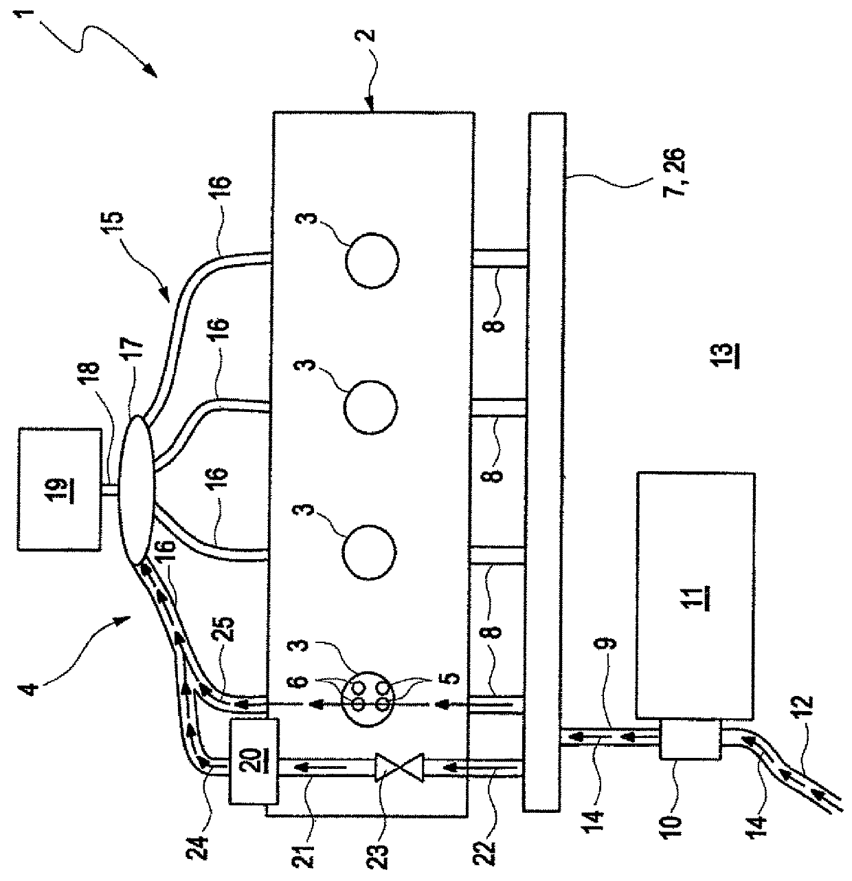
[0026]The FIGURE shows a schematic representation of a drive device 1 with an internal combustion engine 2, which has multiple cylinders 3, and with an exhaust gas system 4. Each cylinder 3 has at least one inlet valve 5 and at least one outlet valve 6. The inlet valves 5 of the cylinders 3 are connected to the air distributor 7, which is preferably constructed as a common air distributor. For this purpose connection lines 8 are provided. The air distributor 7 is fluidly connected to a compressor 10 via a line 9, which compressor can for example be driven by means of an electric motor 11. In addition or as an alternative the compressor 10 can also be a part of a charger, in particular an exhaust gas turbo charger or a blower. On the side facing away from the air distributor 7, the compressor 10 is fluidly connected to an external environment 13 of the drive device 1 via a line 12. By means of the compressor 10 the fresh air can thus be suctioned from the external environment 13 and ...


PUM


Abstract

A method for operating a drive device includes heating a hot air stream with a heating device integrated in a cylinder head of an internal combustion engine of the drive device, wherein the internal combustion engine is connected with an exhaust gas system; mixing the hot air stream upstream of a catalytic converter with a cold fresh air stream for adjusting a defined temperature of the hot air stream; and supplying the hot air stream having the adjusted defined temperature to the catalytic converter in at least one operating state of the internal combustion engine so as to heat the catalytic converter.

Description

CROSS-REFERENCES TO RELATED APPLICATIONS[0001]This application is the U.S. National Stage of International Application No. PCT / EP2014 / 000147, filed Jan. 21, 2014, which designated the United States and has been published as International Publication No. WO 2014 / 114443 and which claims the priority of German Patent Application, Serial No. 10 2013 001 080.2, filed Jan. 23, 2013, pursuant to 35 U.S.C. 119(a)-(d).BACKGROUND OF THE INVENTION[0002]The invention relates to a method for operating a drive device with an internal combustion engine and with an exhaust gas system connected to the internal combustion system, which exhaust gas system has at least one catalytic converter to which a hot air stream which is heated by means of a heating device is supplied for heating. The invention also relates to a drive device.[0003]The drive device serves for example for driving a motor vehicle. The drive device can be a part of a hybrid drive device, which beside the drive device has at least one...

Claims


Application Information

Patent Timeline
Patent Type & Authority Patents(United States)
IPC IPC(8): F01N3/00F01N3/02F01N3/30F02D41/00F01N3/32F02D41/02F02B39/10
CPCF01N3/306F01N3/323F01N3/326F02B39/10F02D41/0255F02D41/0087Y02T10/26F01N2240/14F01N2430/02F02D41/0007Y02T10/12
Inventor GORGEN, MICHAELSONNER, MARKUS
Owner AUDI AG
Why Eureka
Try Eureka