

Heat sink
a heat sink and heat sink technology, applied in the field of heat sinks, can solve the problems of high cost of extrusion equipment, slow process, and compromise of extrusion toleran
- Summary
- Abstract
- Description
- Claims
- Application Information
AI Technical Summary
Benefits of technology
Problems solved by technology
Method used
Image

Examples
first embodiment
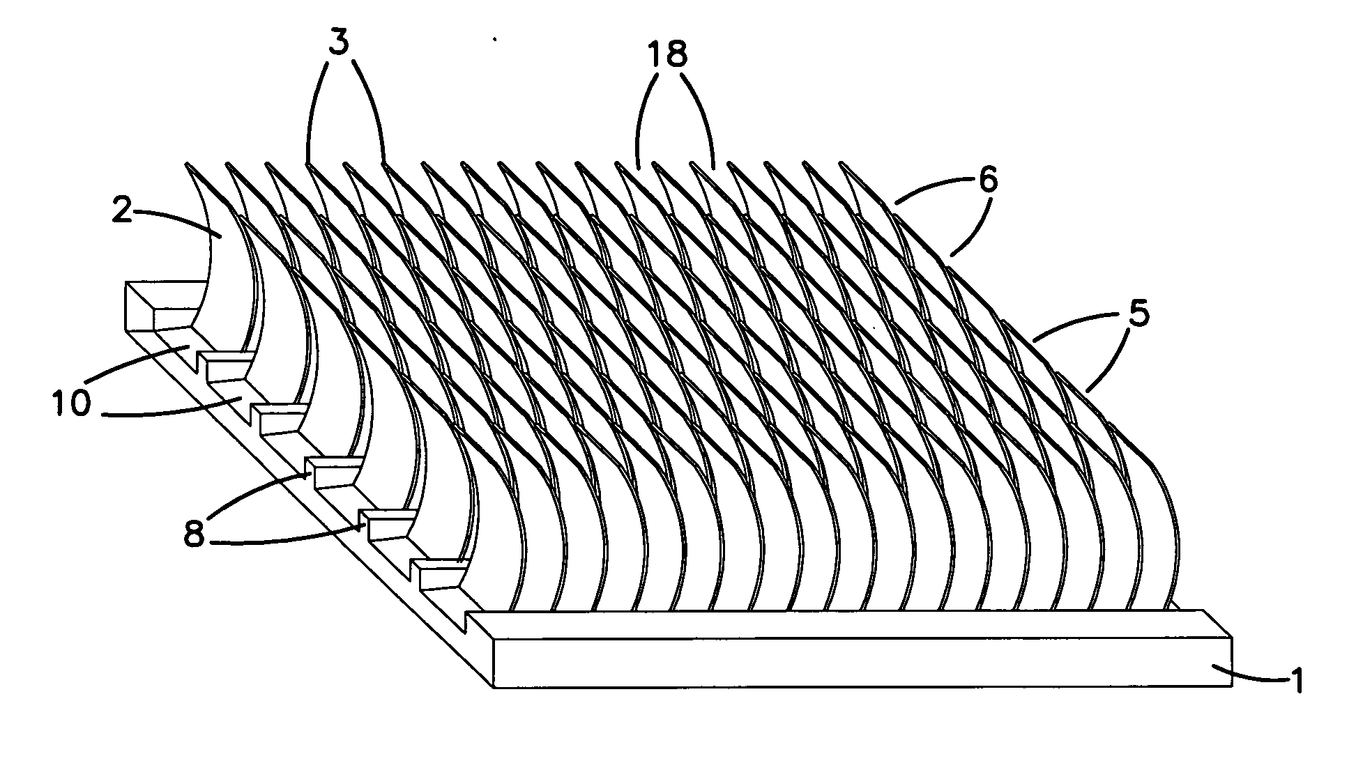
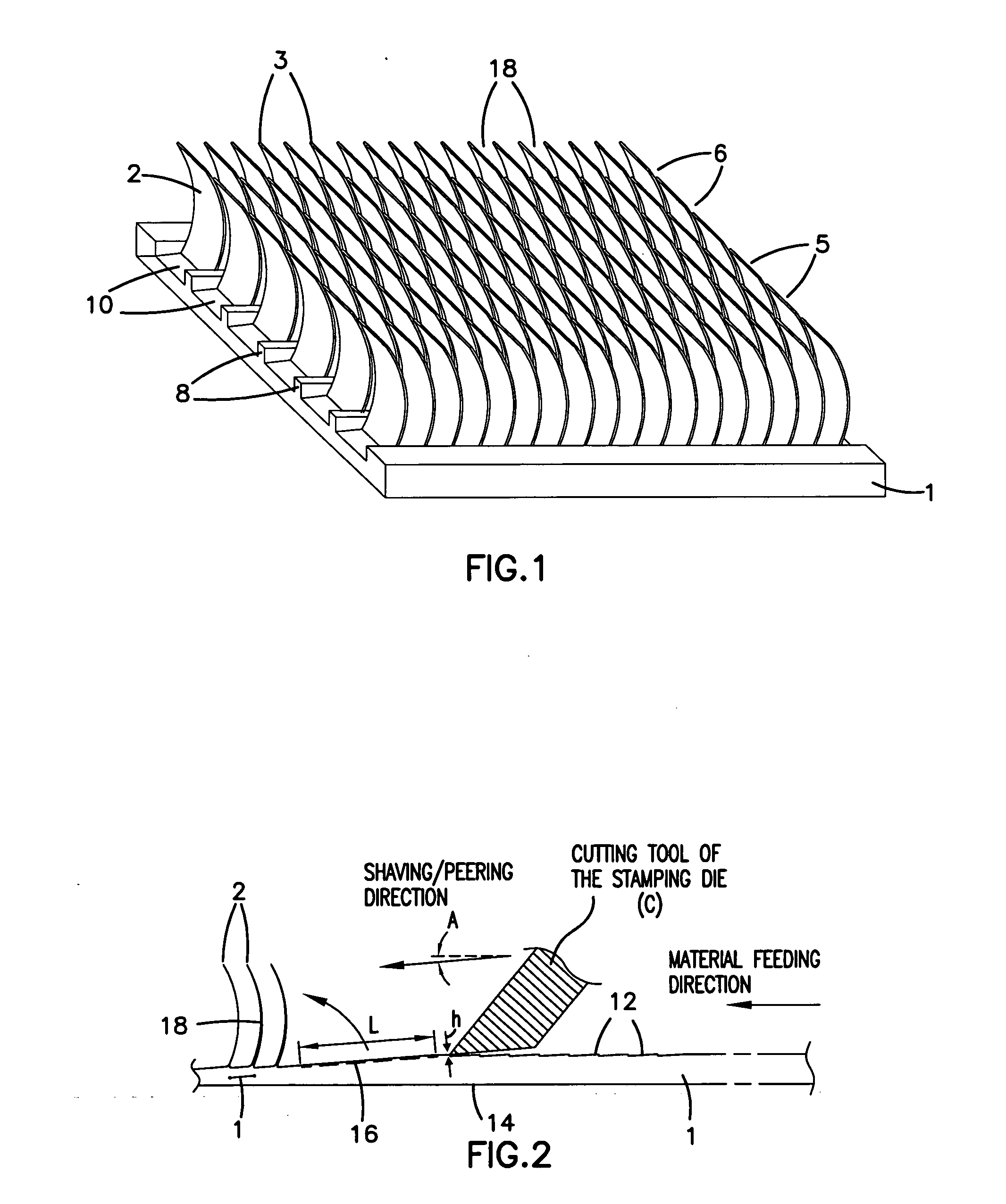
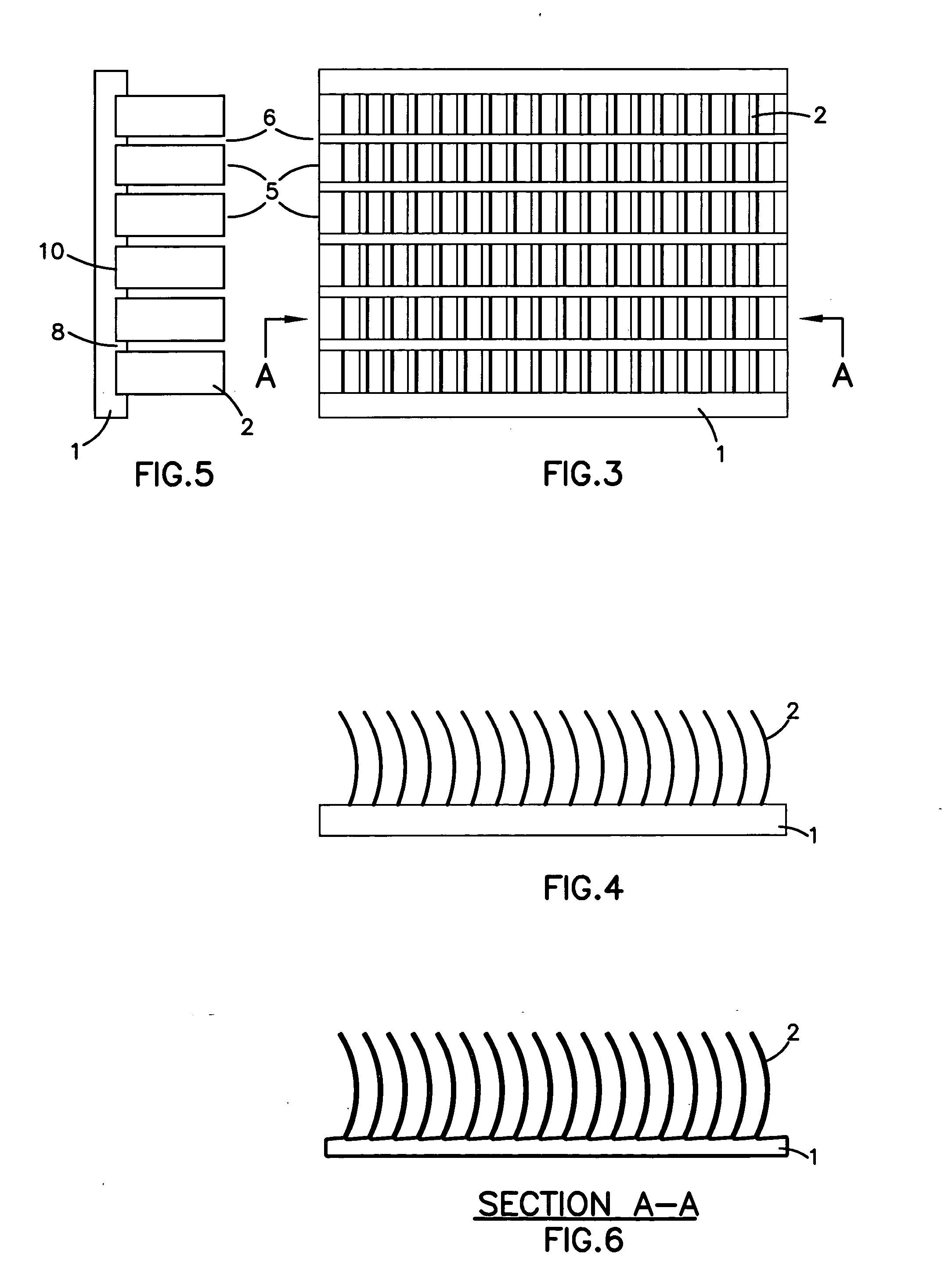
[0031] FIGS. 1 to 6 show the present invention. The heat sink comprises a base or substrate 1, being a block of metal such as aluminium or copper. Layers of the substrate 1 are peeled or shaved away successively in order to form heat dissipative fins 2. The fins 2 may be formed in a series of columns 3 and rows 5. The fins 2 of each column 3 may be formed simultaneously. The rows 5 of fins 2 are separated by a gap 6. Between the rows 5 of fins 2 a rib 8 is present. Between each rib 8 is a groove 10, which is formed as the fins 2 are cut from the substrate 1.
[0032] The fins 2 are arcuate. The arc of each fin 2 illustrated represents approximately {fraction (1 / 8)} of a circle. The arc profile depends on the design of the tool that forms the fins 2, and the thickness and height of the fins 2.
[0033] FIG. 2 shows how a heat sink is formed from substrate 1. Initially, the substrate 1 is a cuboid.
[0034] A cutting tool C of a stamping die tooling engages the substrate 1 to form the fin 2 fr...
third embodiment
[0042] FIG. 8 shows the invention wherein a single row 5" of fins 2" is formed.
[0043] FIG. 9 shows a fourth embodiment, which is small modification of the third embodiment. In the fourth embodiment the fins 2"' are formed across the full width of the substrate 1 rather than leaving a rib 8 at each side, as in the first, second and third embodiments.
[0044] FIG. 10 is a side elevational view of the heat sink of FIG. 9.
[0045] The pitch 18 of the fins 2 according to the embodiments of the present invention and the thickness and height of the fins 2 can be varied within a larger range than is possible using a conventional processes such as extrusion process.
[0046] Also, the process according to the embodiments produces heat sinks faster than the processes of producing an extrusion heat sink, folder type and bonded type heat sink according to the prior art and at lower cost.
[0047] Further, compared with the prior art extrusion process, the bottom surface 14 of the substrate 1 will be rela...
PUM
| Property | Measurement | Unit |
|---|---|---|
| Length | aaaaa | aaaaa |
Abstract
Description
Claims
Application Information