Suspension fitting for a motor vehicle exhaust system, and a vehicle fitted therewith

Inactive Publication Date: 2002-02-07
HUTCHINSON SA
View PDF0 Cites 2 Cited by
  • Summary
  • Abstract
  • Description
  • Claims
  • Application Information

AI Technical Summary

Benefits of technology

0006] The present invention seeks in particular to mitigate this drawback of prior art suspension fittings, by prop

Problems solved by technology

It gives general satisfaction from the functional point of

Method used


Image

  • Suspension fitting for a motor vehicle exhaust system, and a vehicle fitted therewith
  • Suspension fitting for a motor vehicle exhaust system, and a vehicle fitted therewith
  • Suspension fitting for a motor vehicle exhaust system, and a vehicle fitted therewith

Examples


Example

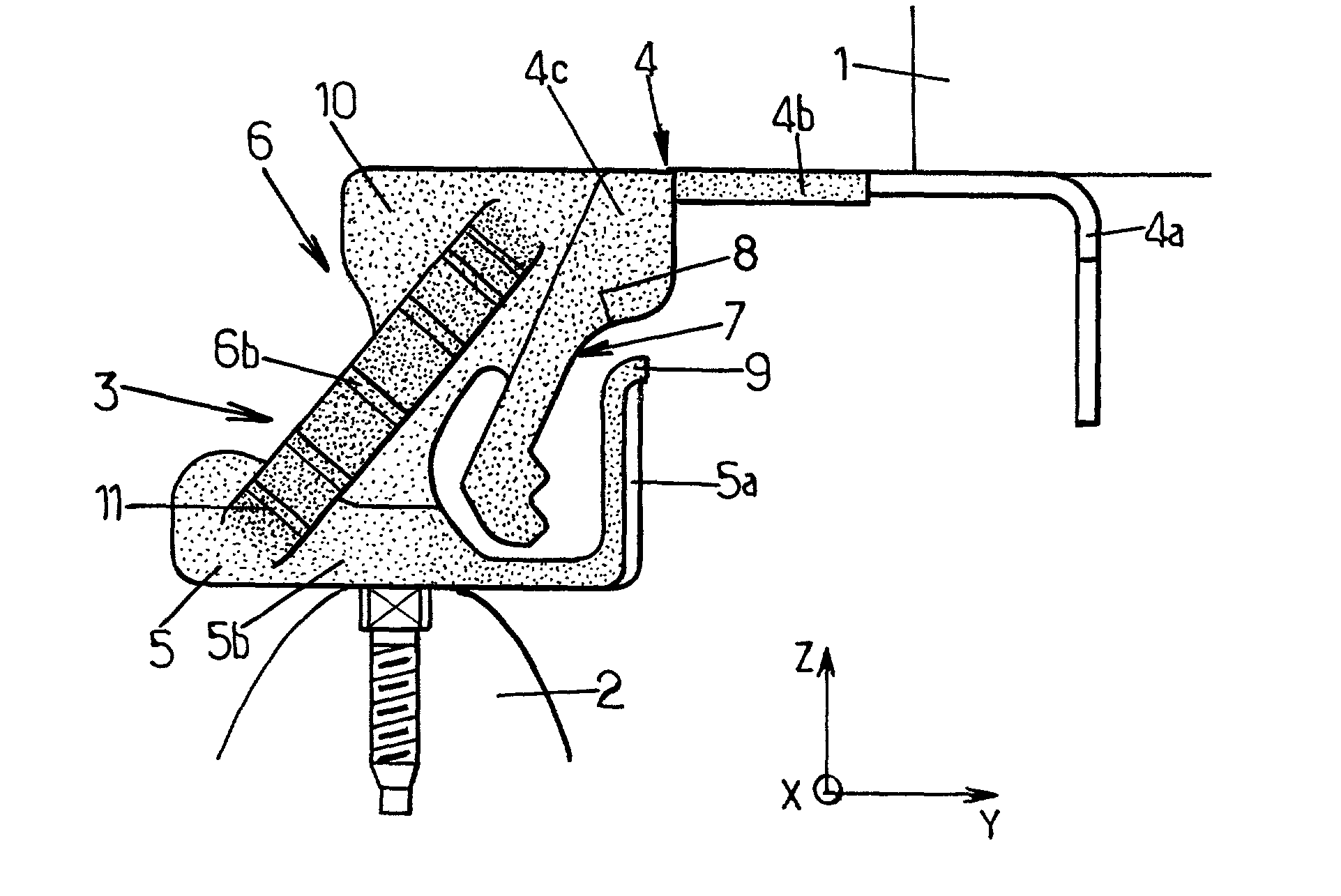
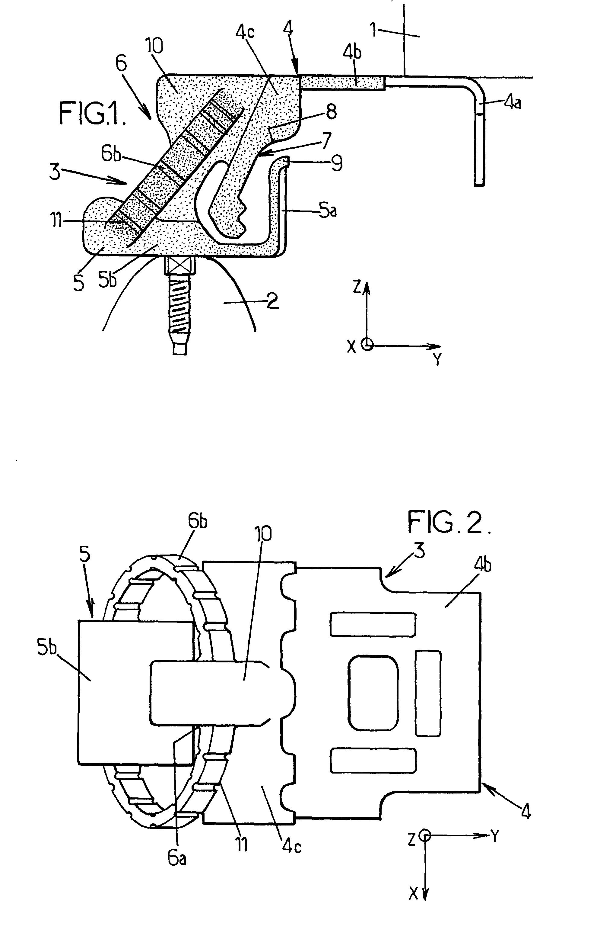
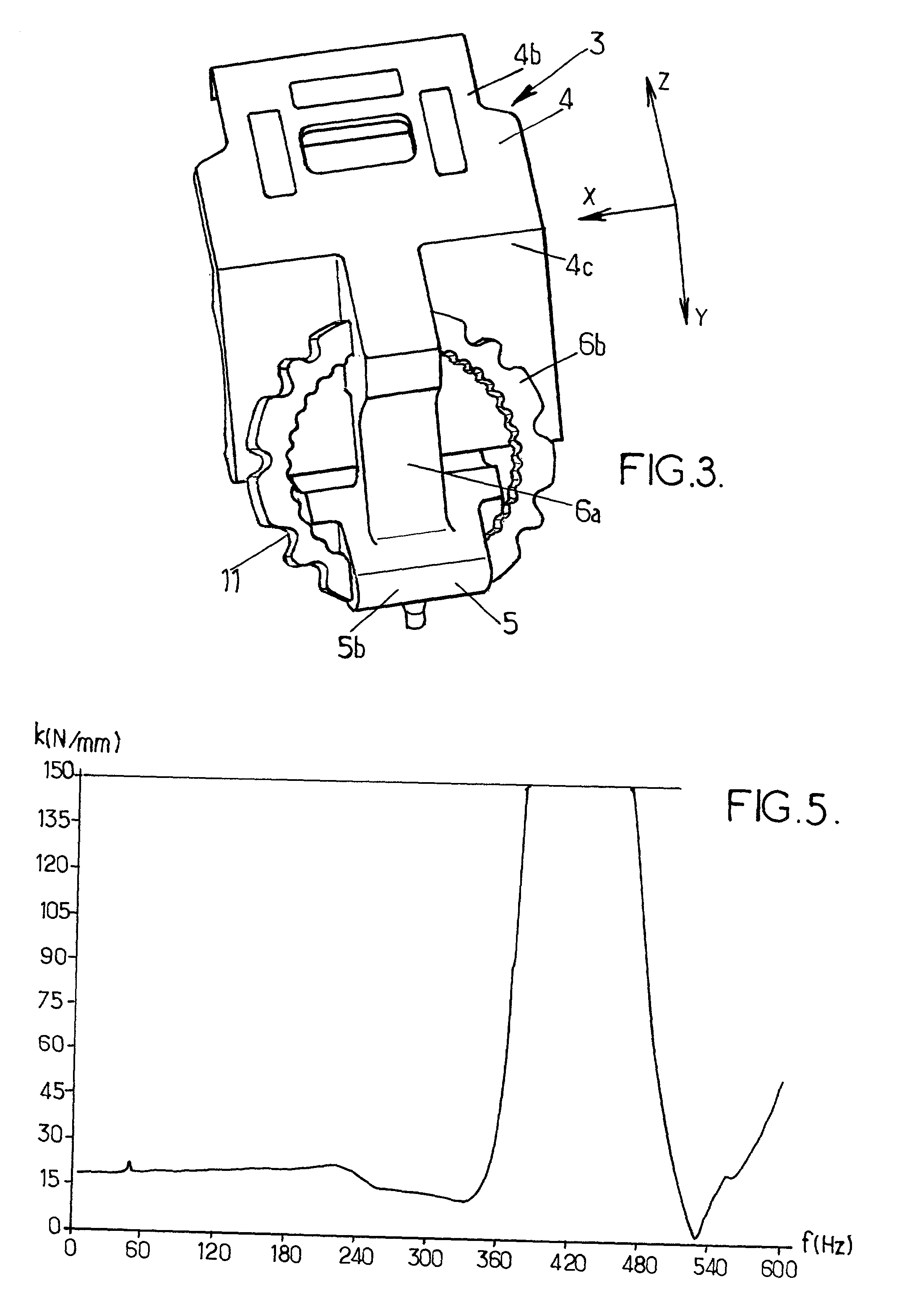
[0027] In the various figures, the orientation of the suspension fitting in three dimensions is identified by three mutually perpendicular axes: Z for the vertical direction, Y for the horizontal transverse direction, and X for the horizontal axial direction (i.e. along the axis of the vehicle, substantially colinear with the general axis of the exhaust system).

[0028] In FIGS. 1, 2, and 4, reference 1 designates the bodywork of the vehicle (and can be constituted in particular by its side members or rails), reference 2 designates the exhaust system (in the vicinity of its silencer or muffler), and reference 3 designates the suspension fitting connecting the exhaust system to the bodywork of the vehicle.

[0029] The fitting 3 is constituted:

[0030] by a top strength member 4 for connection to the bodywork of the vehicle 1;

[0031] by a bottom strength member 5 for connection to the exhaust 2; and

[0032] by a resilient elastomer unit 6 interconnecting the two strength members 4 and 5.

[0033]...


PUM


Abstract

A suspension fitting for a motor vehicle exhaust system, the fitting comprising a top and bottom strength members interconnected by a resilient system comprising firstly a single central support arm and secondly a flexible limiting ring surrounding the support arm to limit relative travel between the strength members in a direction corresponding to the support arm lengthening. The top and bottom strength members have respective downwardly and upwardly extending rigid limbs which are placed facing each other on a horizontal axis perpendicular to the general direction of the exhaust system so as to come into abutment against each other and limit relative travel between the strength members along the axis.

Description

[0001] The present invention relates to suspension fittings for motor vehicle exhaust systems, and to vehicles fitted therewith.[0002] More particularly, the invention relates to a suspension fitting for a motor vehicle exhaust system, the fitting comprising a rigid top strength member suitable for being secured to the bodywork of the vehicle and a rigid bottom strength member suitable for being secured to an exhaust system which extends longitudinally in a general direction parallel to a first axis, these two strength members being connected to each other by a resilient unit made of elastomer and comprising:[0003] firstly a central support arm adapted to support traction forces along a second axis and to filter and damp relative vibratory motion between the top and bottom strength members, said support arm being disposed perpendicularly to the first axis and extending at an angle between a top secured to the top strength member and a bottom secured to the bottom strength member, sa...

Claims


Application Information

Patent Timeline
IPC IPC(8): B60K13/04F01N13/18F16L55/035
CPCB60K13/04F01N13/1822F16L55/035
Inventor MONNEAU, JEAN-PIERRE
Owner HUTCHINSON SA
Why Eureka
Try Eureka