
Modifying message data and generating random number digital signature within computer chip

a random number and message data technology, applied in the field of entity authentication, can solve the problems of exposing the secret or biometric value itself to a greater risk of theft, fraudulent use of a private key to generate a digital signature of an ec, and currently cannot be detected

Inactive Publication Date: 2002-02-07
FIRST DATA
View PDF99 Cites 175 Cited by
  • Summary
  • Abstract
  • Description
  • Claims
  • Application Information

AI Technical Summary

Benefits of technology

0065] Random numbers are utilized in may computer applications, such as in security protocols like secure socket layer (SSL) protocol and pretty good privacy (PGP) for the creation of session keys. Yet another feature of the present invention includes the generation of a digital signature using a digital signature algorithm, with the resulting digital signature being used in such an application as a random number.
0066] The device of the methods of the present invention preferably is a personal device of the sender of the EC. The device also preferably includes a device interface such as, for example, an alphanumeric keypad, an electrical contact, a touch screen display, a standard electronic interface with a computer bus, or an antenna. The device interface also may comprise a port the device, such as a wireless communic

Problems solved by technology

A fraudulent use of a private key to generate a digital signature of an EC currently cannot be detected through the above-described Message Authentication and Factor A Entity Authentication procedures.
The digital signature system therefore is susceptible to fraud if a private key of a device is stolen, either by discovery of the private key therein and subsequent copying and use in another device capable of generating digital signatures, or by physical theft of the device containing the private key.
While Factor B Entity Authentication and Factor C Entity Authentication both reduce the risk of a fraudulent use of a device to generate a digital signature for a message, both also include significant drawbacks.
This paradigm also exposes the Secret or biometric value itself to a greater risk of theft.
First, the transmission of the Secret or biometric value for verification carries with it the risk of interception and discovery during transit.
Second, the Secret or biometric value must be safeguarded by the recipient, thereby exposing the Secret to theft from the recipient.
This is especially significant in the corporate context where a rogue employee may steal the safeguarded Secret or biometric value (insider fraud historically has been the greatest risk).
The potential damages also are extensive when the Secret or biometric value is stolen under this paradigm.
Since it is difficult for an individual to remember multiple Secrets for multiple recipients, it is common for the same Secret to be used by an individual with different recipients.
The theft of the Secret from one credit card company puts all of the other credit card accounts at jeopardy, at least until the Secret is changed.
In the case of the theft of a biometric value, the damages are even more severe, as a person's biometric characteristic cannot be changed and, once lost, potentially compromises any future entity authentication therewith.
A drawback to this alternative paradigm, however, is that because the device remains inoperable until the correct Secret or biometric value of the user is entered, the recipient is unable to monitor repeated attempts to guess the Secret or biometric value.
Under this alternative paradigm, a recipient is unable to determine whether a particular EC sent during such a time period includes a fraudulently generated digital signature, as the device may have been stolen after being enabled but before its deactivation.
Yet another drawback is that this alternative paradigm does not particularly accommodate the use of the device to send ECs to different recipients when a biometric value is prestored and maintained within--and Factor C Entity Authentication is performed by--the device.

Method used


Image

  • Modifying message data and generating random number digital signature within computer chip
  • Modifying message data and generating random number digital signature within computer chip
  • Modifying message data and generating random number digital signature within computer chip

Examples


embodiment 200

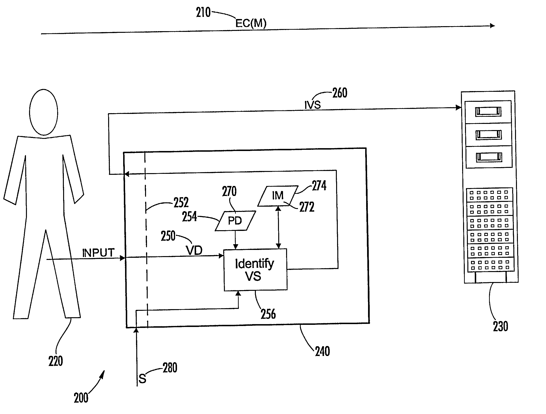
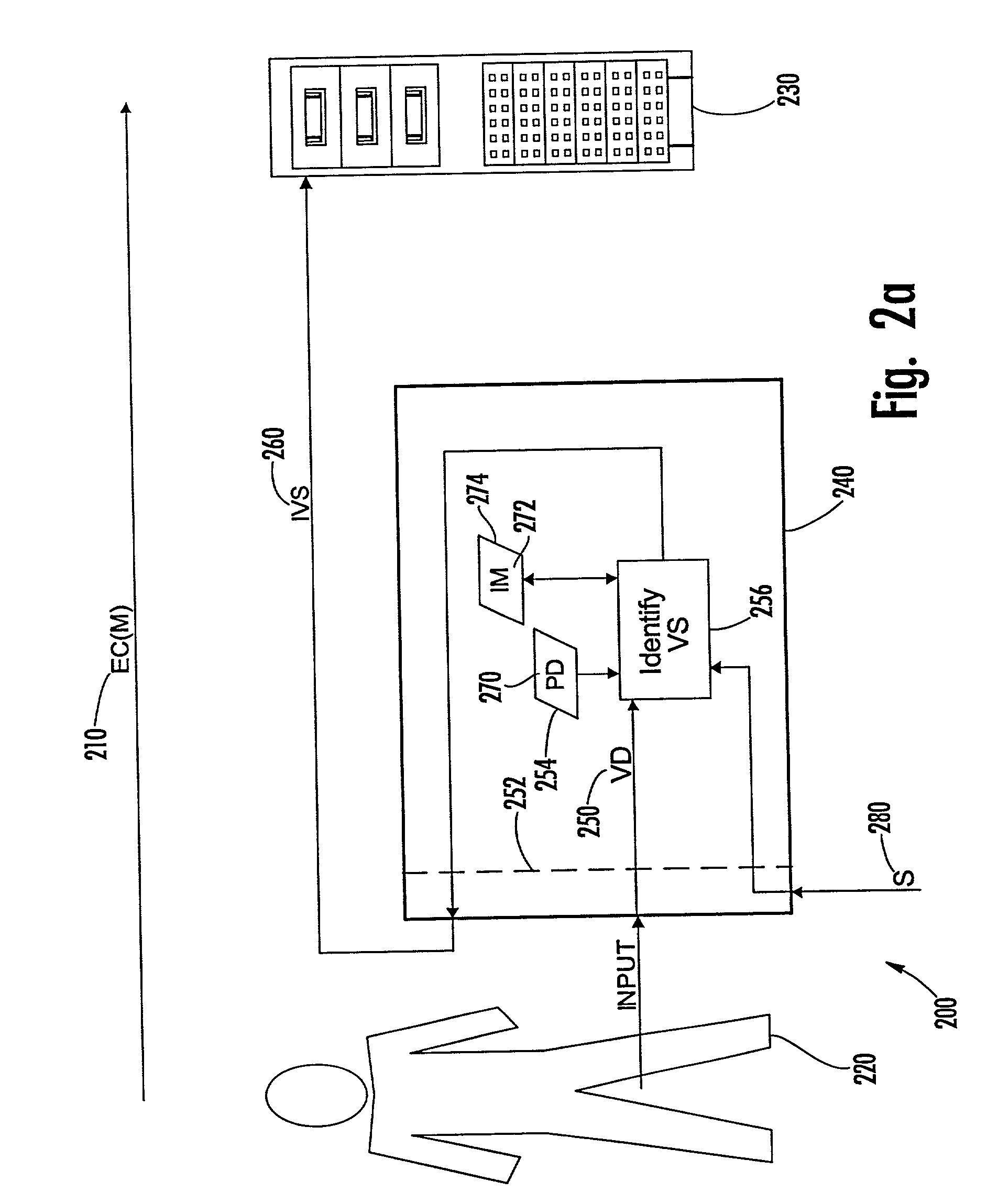
[0132] A first preferred embodiment 200 of the present invention is illustrated in FIG. 2a, wherein an EC 210 including a message from a sender 220 is received by a recipient represented by an electronic apparatus 230, and wherein a device 240 receives input representing verification data (VD) 250 at a device interface 252. The device 240 includes a verification component therein that maintains data (PD) 270 of the sender 220 prestored in memory 254 of the device 240. The verification data 250 and prestored data 270 represent Secret or biometric values.

[0133] The verification component identifies at 256 a current verification status of the device 240 based on a comparison of the verification data 250 with the prestored data 270. Upon receipt of a signal (S) 280, the last identified (i.e., "current") verification status of the device 240 is communicated to the recipient by outputting from the device 240 an indicator 260 that then is transmitted to the recipient in association with th...

embodiment 400

[0144] A second preferred embodiment 400 of the present invention is illustrated in FIG. 4a, wherein an EC 410 including a message from a sender 420 is received by a recipient represented by an electronic apparatus 430, and wherein a device 440 receives input representing verification data (VD) 450 at a device interface 452. The device 440 includes a verification component therein that maintains data (PD) 470 of the sender 420 prestored in memory 454 of the device 440. The verification data 450 and prestored data 470 represent Secret or biometric values.

[0145] The verification component identifies at 456 a current verification status of the device 440 based on a comparison of the verification data 450 with the prestored data 470. Upon receipt of a signal (S) 480, the last identified (i.e., "current") verification status of the device 440 is communicated to the recipient by outputting from the device 440 an indicator 460 that then is transmitted to the recipient in association with t...

embodiment 600

[0158] A third preferred embodiment 600 of the present invention is illustrated in FIG. 6a, wherein an EC 610 including a message from a sender 620 is received by a recipient represented by an electronic apparatus 630, and wherein a device 640 receives input representing verification data (VD) 650 at a device interface 652. The device 640 includes a verification component therein that maintains data (PD) 670 of the sender 620 prestored in memory 654 of the device 640. The verification data 650 and prestored data 670 represent Secret or biometric values.

[0159] The verification component identifies at 656 a current verification status of the device 640 based on a comparison of the verification data 650 with the prestored data 670. Upon receipt of a signal (S) 680, the last identified (i.e., "current") verification status of the device 640 is communicated to the recipient by outputting from the device 640 an indicator 660 that then is transmitted to the recipient in association with th...


PUM


Abstract

A method of generating a digital signature within a computer chip includes receiving data representing a message, and generating a digital signature for the message by modifying the message data with additional data, calculating a hash value of the modified message, and encrypting the hash value using a private key of a public-private key pair. The additional data includes data prestored within content searchable memory of the computer chip and a verification status of the computer chip. The verification status is identified out of a plurality of predefined verification statuses as a function of verification data input into the computer chip and data prestored within the computer chip. An identified verification status is used by one entity in determining risk regarding an electronic communication from another entity, especially where the electronic communication comprises a request and a digital signature generated by the computer chip.

Description

I. CROSS-REFERENCE TO RELATED APPLICATIONS[0001] This patent application claims priority in the United States under 35 U.S.C. 119, and under the Paris Convention worldwide, to the benefit of the filing date of Wheeler et al. U.S. provisional patent application serial No. 60 / 223,076, which was filed on Aug. 4, 2000, and which is incorporated herein by reference. This application also incorporates herein by reference each of four international patent applications and two U.S. patent application to Anne and Lynn Wheeler filed concurrently herewith on Aug. 6, 2001, in the U.S. Patent & Trademark Office and bearing serial number PCT / US______ / ______(entitled "Person-Centric Account-Based Digital Signature System") and serial number 09 / _______,_______ (entitled "Account-Based Digital Signature (ABDS) System"); serial number PCT / US_______ / _______(entitled "Entity Authentication in Electronic Communications by Providing Verification Status of Device"); serial number PCT / US______ / ______(enti...

Claims


Application Information

Patent Timeline
IPC IPC(8): G06F12/14G06F19/00G06F21/00G06F21/32G06F21/34G06Q20/00G07F7/10G09C1/00H04L9/00H04L9/10H04L9/32H04L29/06
CPCG06F21/32G06F2221/2113G06Q20/00G06Q20/02G06Q20/04G06Q20/0855G06Q20/12G06Q20/341G06Q20/3558G06Q20/3674G06Q20/3676G06Q20/382G06Q20/3821G06Q20/3823G06Q20/3825G06Q20/3829G06Q20/385G06Q20/388G06Q20/4014G06Q20/40145G06Q20/403G06Q20/40975G06Q50/188G07F7/0886G07F7/1008G07F7/1016H04L63/0428H04L63/0442H04L63/062H04L63/0823H04L63/083H04L63/12H04L9/321H04L9/3247H04L2209/42H04L2209/56
Inventor WHEELER, LYNN HENRYWHEELER, ANNE M.
Owner FIRST DATA
Learn More