System and method of preventing aircraft wing damage

a technology of aircraft wings and preventing collisions, applied in the field of aircraft safety systems, can solve the problems of increased encroachment, increased encroachment, and very common collisions of small private aircra

Inactive Publication Date: 2002-02-14
RASTAR CORP
View PDF0 Cites 25 Cited by
  • Summary
  • Abstract
  • Description
  • Claims
  • Application Information

AI Technical Summary

Problems solved by technology

Yet one form of collision that is very common among small private aircraft occurs when the pilot taxies the aircraft.
Airports are often overcrowded with aircraft while the taxiways are small and may be subject to further encroachment by poorly-parked aircraft.
The problem is especially difficult for pilots taxiing in small airports as it is difficult to maneuver the typical 25-40 foot wingspan of a private aircraft amidst a crowded taxiway while keeping the tips from striking other aircraft or obstructions that exist alongside the taxiiway.
Any error in making this distance judgement can lead to damages to both aircraft.
If insufficient maneuver room exists, then the pilot will be generally required to shutdown the aircraft use a tow-bar to back up and reposition the aircraft as few smaller aircraft have reversible thrust propellers.

Method used


Image

  • System and method of preventing aircraft wing damage
  • System and method of preventing aircraft wing damage
  • System and method of preventing aircraft wing damage

Examples


Embodiment Construction

[0035] Referring more specifically to the drawings, for illustrative purposes the present invention is embodied in the apparatus generally shown in FIG. 1 through FIG. 13. It will be appreciated that the apparatus may vary as to configuration and as to details of the parts without departing from the basic concepts as disclosed herein.

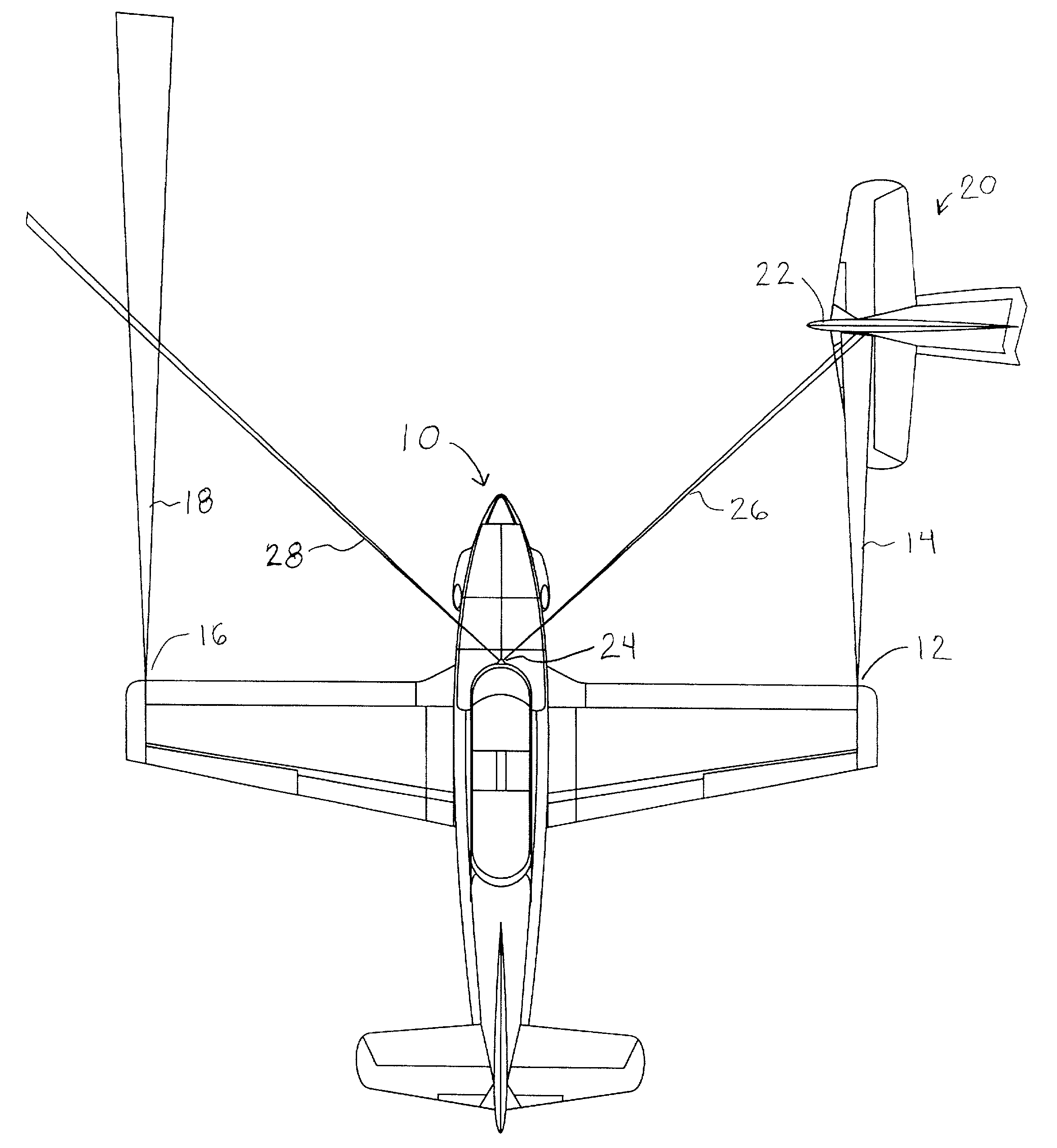
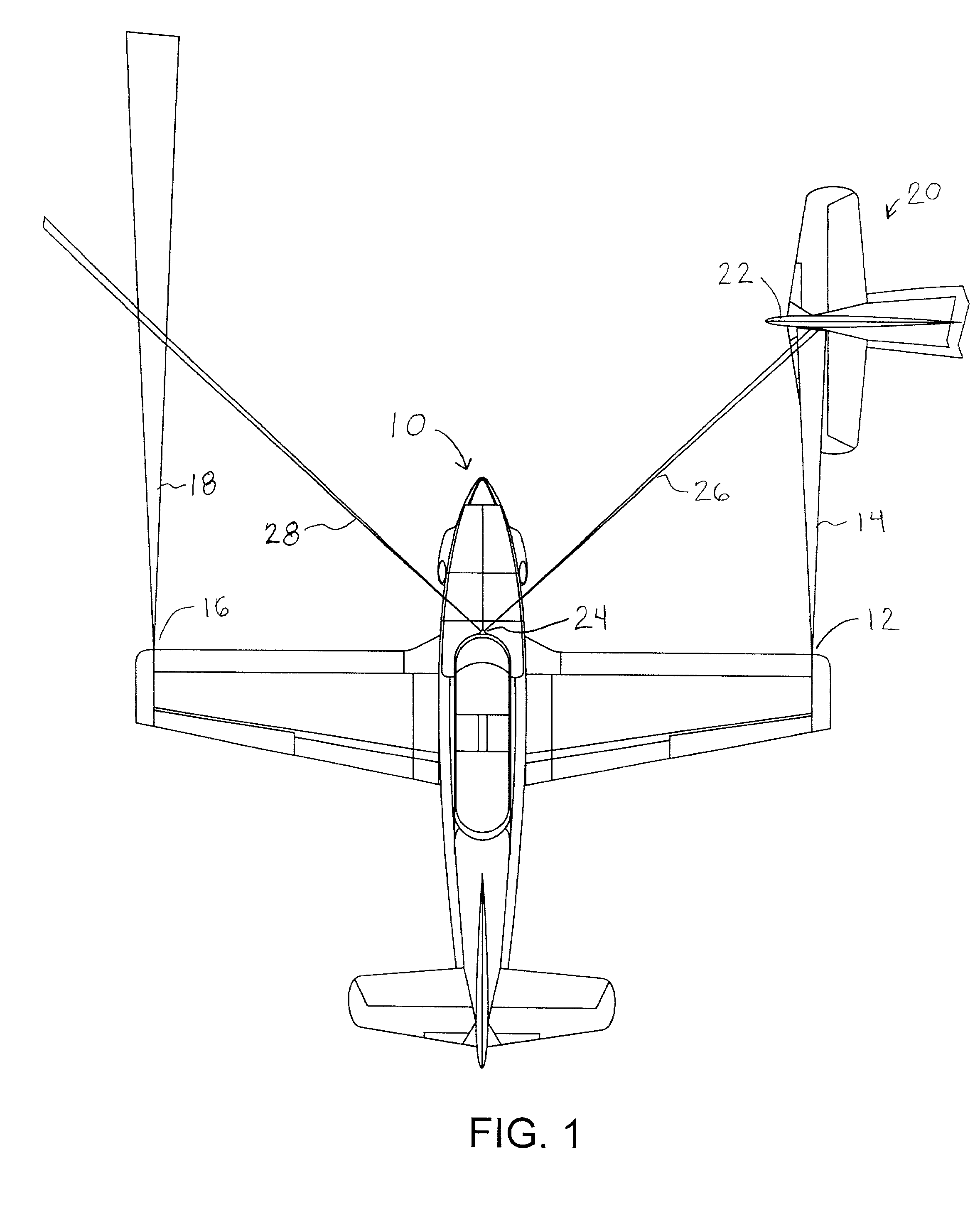
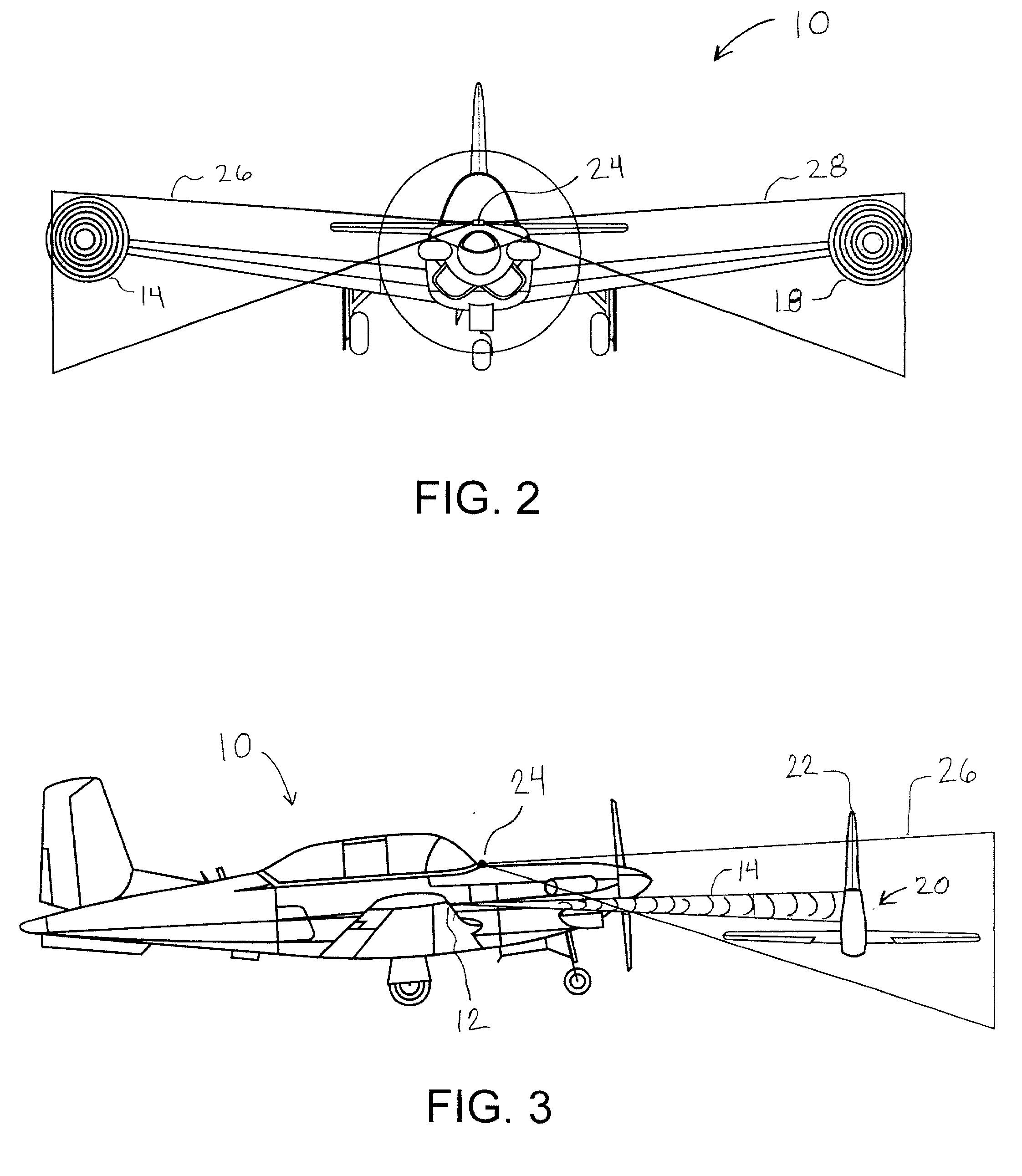
[0036] FIG. 1 illustrates an embodiment of the tip tracking system in use while an aircraft 10 taxies toward an obstruction. The illustration depicts a single obstruction being designated by the system, however, it will be appreciated that in general the pilot has sporadically spaced obstructions on each side and is attempting to navigate a path between the obstructions, a path in which the wing tips will not contact obstructions on either side. The tip tracking system comprises a first wingtip light pattern projection source 12, such as a laser, which casts a beam 14, a second wingtip light pattern projection source 16 which casts a beam 18. Beam 14 in...


PUM


Abstract

An apparatus and method for tracking aircraft wingtip position during taxi operations to prevent collisions with nearby obstructions. A patterned illumination source is attached proximal the wingtips to project a readily discernable target pattern in the direction of taxi travel. At least a portion of the target pattern is reflected off of any obstructions that lie in the straight-line direction of travel, such that the pilot can maneuver to avoid striking the obstruction. By way of example, the patterned illumination source comprises a laser module positioned with the navigation and/or strobe light of the aircraft that is configured to project a circular pattern in front of the wingtip. The device may be retrofitted to existing aircraft without additional wiring with the control of activation being selectable via power cycling of existing aircraft lighting controls.

Description

[0001] This application claims priority from U.S. Provisional Application Ser. No. 60 / 203,564 filed on May 11, 2000.STATEMENT OF FEDERALLY SPONSORED RESEARCH OR DEVELOPMENT[0002] Not ApplicableREFERENCE TO A MICROFICHE APPENDIX[0003] Not Applicable[0004] 1. Field of the Invention[0005] This invention pertains generally to aircraft safety systems and more particularly to a system and method for preventing collisions between the wingtips of an aircraft moving on the ground and obstructions.[0006] 2. Description of the Background Art[0007] Moving aircraft are subject to a variety of situations in which a collision may occur. Recently, advanced GPS systems have been proposed to assure separation between aircraft along their flight paths. Yet one form of collision that is very common among small private aircraft occurs when the pilot taxies the aircraft. Airports are often overcrowded with aircraft while the taxiways are small and may be subject to further encroachment by poorly-parked a...

Claims


Application Information

Patent Timeline
Patent Type & Authority Applications(United States)
IPC IPC(8): B64D47/04G08G5/06
CPCB64D47/04G08G5/0021G08G5/065
Inventor RAST, RODGER H.
Owner RASTAR CORP
Why Eureka
Try Eureka