
Machining tool for manufacturing radial bearings, and manufacturing apparatus and manufacturing method using the same

a technology for radial bearings and manufacturing tools, which is applied in the direction of manufacturing tools, sliding contact bearings, mechanical equipment, etc., can solve the problems of reducing productivity, affecting the quality of bearings, etc., and achieves the goal of obtaining high-performance bearing members at low cost. , the effect of reducing the cost of production

Inactive Publication Date: 2002-02-21
NIDEC CORP
View PDF0 Cites 8 Cited by
  • Summary
  • Abstract
  • Description
  • Claims
  • Application Information

AI Technical Summary

Benefits of technology

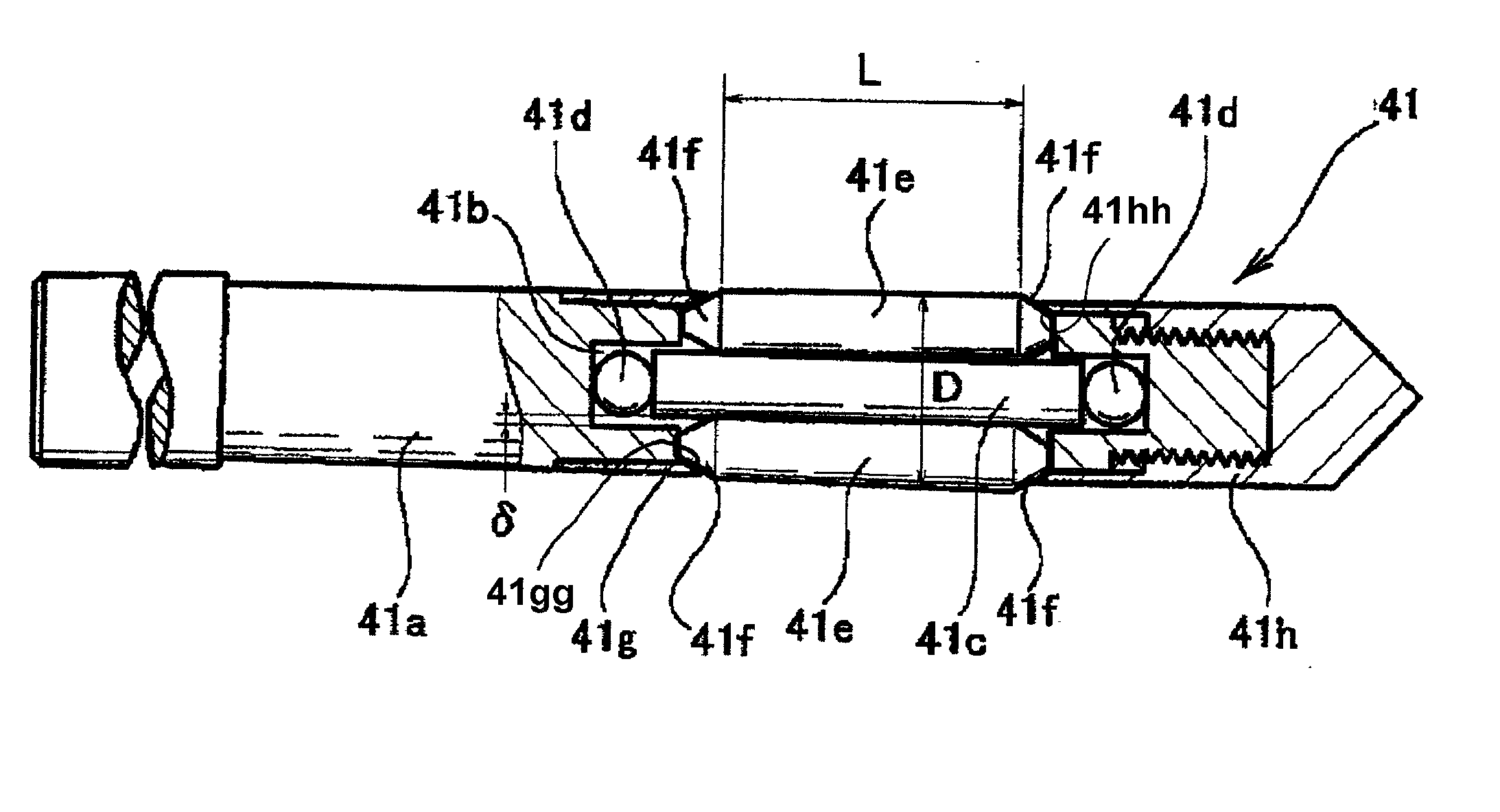
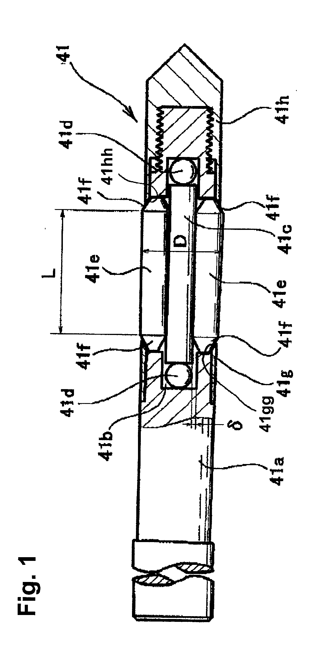
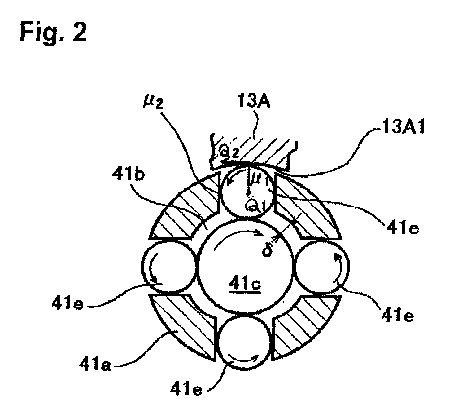
[0009] In accordance with one embodiment of the present invention, a gap .delta. may be formed in the radial direction between the outer circumference of the rotatable core piece member and the inner circumference surface of the hollow storage section of the tool shaft main body member that would allow free movement of the rotatable core piece member, such that the movement of the rotatable core piece member in the radial direction and / or in the shaft tilt direction can be made easily and reliably using the gap in the radial direction.
[0010] Furthermore, in accordance with one embodiment of the present invention, the roll machining surface of each of the roll machining members may have a length L in the axial direction that is the same or longer than a machining diameter D that is defined by a circle connecting the outer most circumference surfaces of roll machining surfaces of the roll machining members. As a result, the roll machining members would abut against the inner circumference surface of the bearing hole in the range of the length L in the axial direction and be able to move in the radial direction or tilt in the axial direction within this abutting range. This causes the uniform velocity rotation of the roll machining members to be conveyed well to the inner circumference surface of the bearing hole and ensures the automatic center-aligning action to take place.

Problems solved by technology

When trying to achieve a higher precision finishing in particular with a dynamic pressure bearing device, the processing time increases dramatically and an expensive comb tooth-shaped high precision automatic lathe must be used, which considerably reduce productivity.
In addition, due to such problems in machining, there are substantial limitations in the bearing characteristics of the various bearing members mentioned above, and it is extremely difficult to obtain high-performance bearing members at low costs.

Method used


Image

  • Machining tool for manufacturing radial bearings, and manufacturing apparatus and manufacturing method using the same
  • Machining tool for manufacturing radial bearings, and manufacturing apparatus and manufacturing method using the same
  • Machining tool for manufacturing radial bearings, and manufacturing apparatus and manufacturing method using the same

Examples


Embodiment Construction

[0025] One embodiment of the present invention will be explained below. First, an overall structure of a hard disk drive device (HDD) to which the present invention may be applied will be explained with references to the accompanying drawings.

[0026] A shaft-rotating spindle motor for an HDD shown in FIG. 3 generally includes a stator assembly 10, which is a fixed member, and a rotator assembly 20, which is a rotating member assembled on top of the stator assembly 10. The stator assembly 10 has a fixed frame 11 screwed onto a fixed base (not shown). The fixed frame 11 is formed from an aluminum metal material to reduce its weight. A ring-shaped bearing holder 12 is formed upright in the generally center area of the fixed frame 11. A bearing sleeve 13 in a hollow cylinder shape, which is a fixed bearing member, is attached to an inner circumference of the bearing holder 12 and joined to the bearing holder 12 through press fit or shrink fit. The bearing sleeve 13 is formed from a coppe...


PUM

PropertyMeasurementUnit
surface roughnessaaaaaaaaaa
lengthaaaaaaaaaa
machining diameteraaaaaaaaaa

Abstract

A machining tool for manufacturing a radial bearing, and a manufacturing apparatus and a manufacturing method using the machining tool are provided. The machining tool includes an inner surface finishing tool to finish an inner circumference surface of a bearing hole provided on a radial bearing. The inner surface finishing tool includes a tool shaft main body member that defines a hollow storage section provided within the tool shaft main body member, a rotatable core piece member mounted inside the hollow storage section in a manner to be rotatable within the tool shaft main body member, and a plurality of roll machining members each with a circular cross-sectional roll machining surface. The plurality of roll machining members rollably abut against the outer circumference surface of the rotatable core piece member. The plurality of roll machining members are in contact under pressure with the inner circumference surface of the bearing hole. The rotatable core piece member is movable in the radial direction and can be tilted with respect to the central axis of the tool shaft main body member.

Description

[0001] 1) Field of the Invention[0002] The present invention relates to a machining tool for manufacturing radial bearings, which is used to finish the inner circumference surface of a bearing hole in a radial bearing, and a manufacturing apparatus and a manufacturing method using the same. In particular, the present invention is suitable for use on dynamic pressure bearing devices that require high precision.[0003] 2) Related Art[0004] Rotation drive devices generally use various types of radial bearing, such as, for example, metal bearings, sintered bearings and dynamic pressure bearings. In the manufacture of such radial bearings, the inner surface of a bearing hole is machined, which is usually done by cutting (lathe machining). For example, first, the diameter of a guide hole is enlarged through a rough machining, and in the subsequent finishing the inner circumference surface of the bearing hole is finished to a predetermined precision with a designed inner diameter dimension,...

Claims


Application Information

Patent Timeline
Patent Type & Authority Applications(United States)
IPC IPC(8): B21C37/30B21H1/12B24B39/02B21H7/18B21K1/04B23P9/02B24B39/04F16C17/02F16C33/14
CPCB21C37/30B21H1/12B21H7/187B21K1/04B23P9/02Y10T29/49707Y10T29/49643Y10T29/49639Y10T29/47Y10T29/53104Y10T29/49636B24B39/045
Inventor USUI, MOTONORI
Owner NIDEC CORP
Learn More