Continuity tester for long wires

a technology of continuity tester and long wire, which is applied in the direction of short-circuit testing, air-break switches, instruments, etc., can solve the problems of difficult and time-consuming testing of continuity of wires at telephone switching centers, and the reversal of "ring" and "tip" leads at these locations is difficult and time-consuming, and the process is very time-consuming

Inactive Publication Date: 2002-02-21
HALDEN ROGER D
View PDF0 Cites 3 Cited by
  • Summary
  • Abstract
  • Description
  • Claims
  • Application Information

AI Technical Summary

Benefits of technology

0008] In order that the invention may be clearly understood and readily carried into effect, a preferred embodiment

Problems solved by technology

Testing continuity of wires at a telephone switching center can be very complicated and time consuming because of the large number of wires involved.
Ch

Method used


Image

  • Continuity tester for long wires
  • Continuity tester for long wires
  • Continuity tester for long wires

Examples


Embodiment Construction

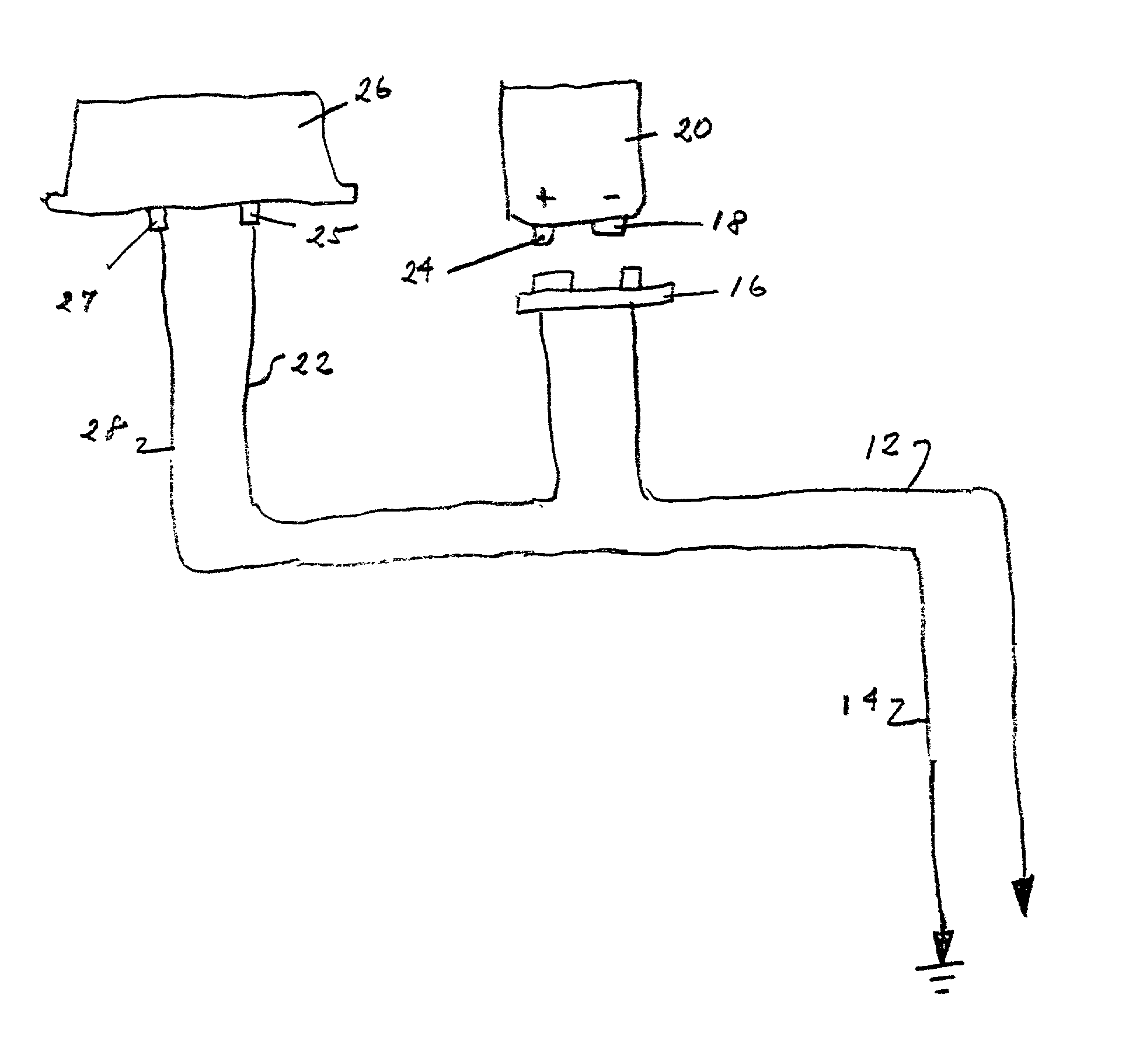
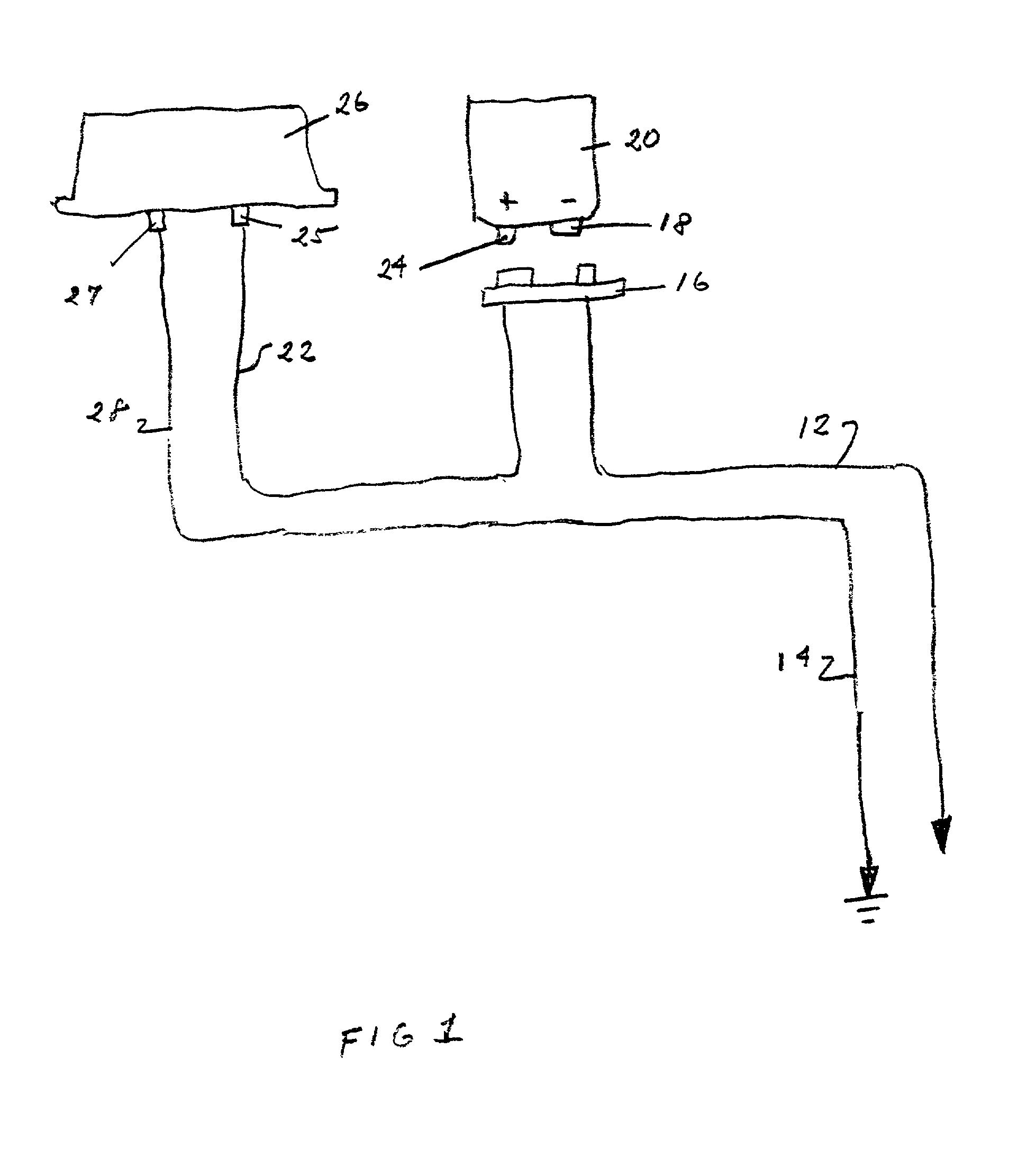
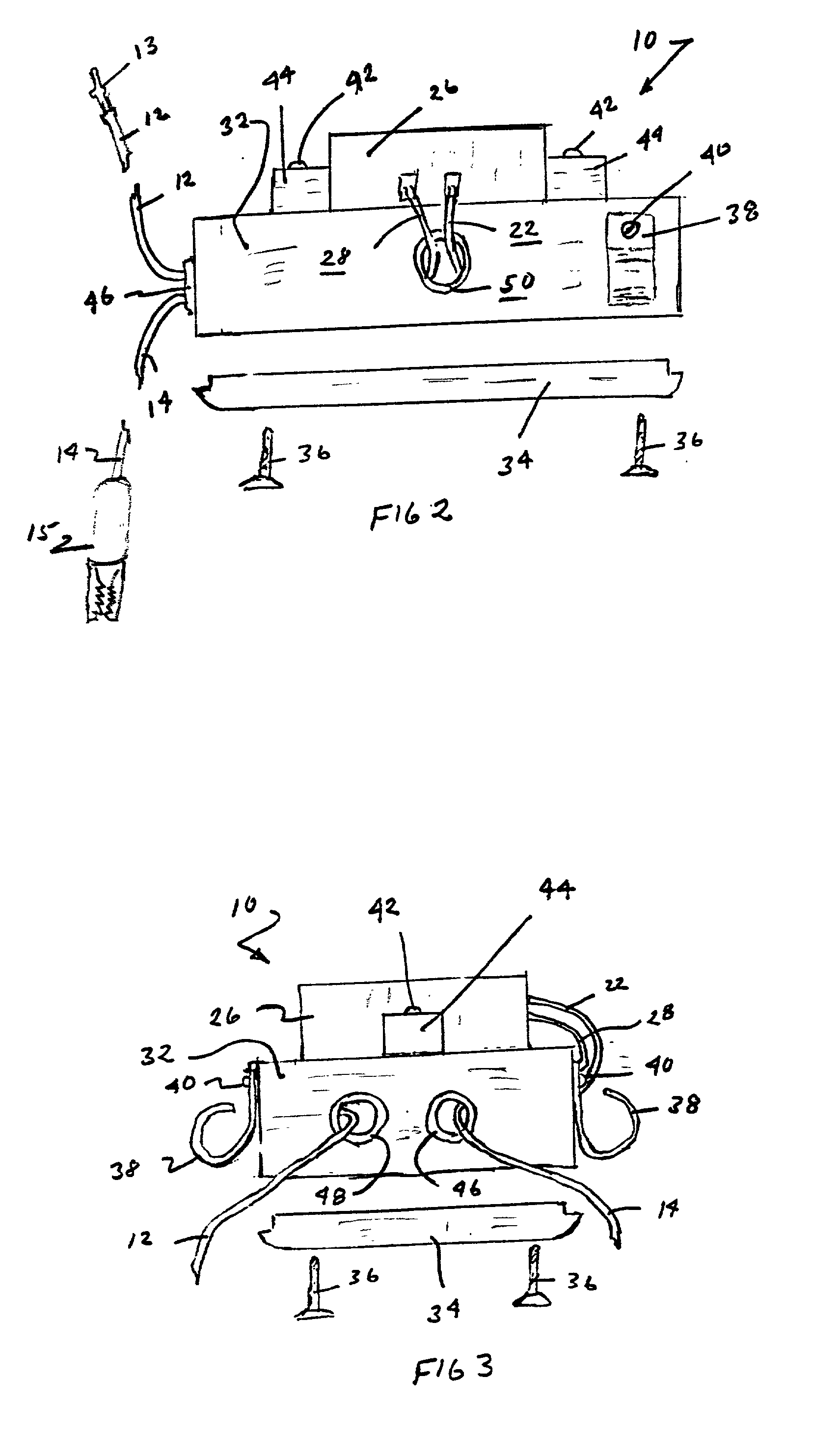
[0016] A continuity tester 10 is shown in FIGS. 2-5. A pair of continuity testers 10 and 11 are used together to test the continuity of a long electrical line. The continuity tester 10 is shown schematically in FIG. 1. There is no separate schematic for tester 11, but the only difference between the two continuity testers 10 and 11 is that the battery polarity is reversed between the two.

[0017] As shown in FIG. 1, the continuity tester 10 includes a lead 12 having a probe end 13 (shown in FIG. 2) to be electrically connected to the wire to be tested, and a ground lead 14 to be electrically connected to a common ground which may include an earth ground. As shown in FIG. 2, lead 14 may have an alligator clip end 15 for connecting lead 14 to ground.

[0018] The lead 12 is connected through a battery connector 16 to the negative terminal 18 of battery 20. In a preferred embodiment, the battery 20 is a conventional 9-volt battery, and the connector 16 is a conventional 9-volt battery conne...


PUM


Abstract

A continuity tester for testing continuity of long electrical lines having two units with one unit located at each end of the line to be tested. A battery is provided with each unit. A ground lead is provided with each unit for connecting the battery through a buzzer to ground. Further, a probe lead is provided for connecting the battery to one end of the line to be tested. The first unit uses the battery with one polarity and the second unit uses the battery with a reversed polarity.

Description

BACKGROUND OF INVENTION[0001] This invention relates to a continuity tester for testing the continuity of long electrical lines, such as telephone cable pairs.[0002] Testing continuity of wires at a telephone switching center can be very complicated and time consuming because of the large number of wires involved. A typical switching center for a telephone system includes banks of wiring blocks located at a Main Distribution Frame ("MDF"). Each of the wiring blocks may have a 100-cable pairs or more.[0003] A cable pair is commonly used in telephone systems for electrically connecting a customer's telephone with the switching center of the telephone company. Each of these pairs includes a "ring" lead and a "tip" lead.[0004] At the MDF, both the "ring" lead and "tip" lead of the cable pair have pins which are exposed in the wiring block. From the MDF, the cable pairs are run to other equipment commonly located on other floors in the switching center building. For example, the wire pai...

Claims


Application Information

Patent Timeline
IPC IPC(8): G01R31/02
CPCG01R31/026G01R31/52G01R31/54
Inventor HALDEN, ROGER D.
Owner HALDEN ROGER D
Why Eureka
Try Eureka