Heart valve prosthesis

a heart valve and prosthesis technology, applied in the field of heart valve prosthesis, can solve the problems of hyperemic zones, inability to fully wash the lateral surfaces using both forward and reverse, and inability to achieve the effect of fully washing the lateral surfaces,

Inactive Publication Date: 2002-02-21
SAMKOV ALEXANDR VASILIEVICH +3
View PDF0 Cites 9 Cited by
  • Summary
  • Abstract
  • Description
  • Claims
  • Application Information

AI Technical Summary

Problems solved by technology

With such a construction, arrangement of the rotation limiters of flaps directly in a hinge area, and contact of their lateral surfaces with flap bearings in open and closed positions do not practically make it possible to fully wash the lateral surfaces using both forward and reverse flows of blood.
This results in the appearance of hyperemic zones, which facilitate the formation of blood clots.
Hydrodynamic investigations go to show that the structure of a direct flow in-between the flaps is not uniform.
The slide of flaps, in opening and / or closing positions, along the extended recesses does not impede thrombosis because it does not remove the hyperemic zones and does not provide for washing the zones of cooperation of the flap bearings with the recesses.
Besides this, the flap bearings may move in an asynchronous manner along an extended recess in closing / opening the valve, a factor that will lead to the prosthesis's unstable work expressed in the fluctuation of values of the forward and reverse flows of blood and in the difference of mechanical forces exerting an influence on the prosthesis's elements, which lowers reliability of its operation.

Method used


Image

  • Heart valve prosthesis
  • Heart valve prosthesis
  • Heart valve prosthesis

Examples


Embodiment Construction

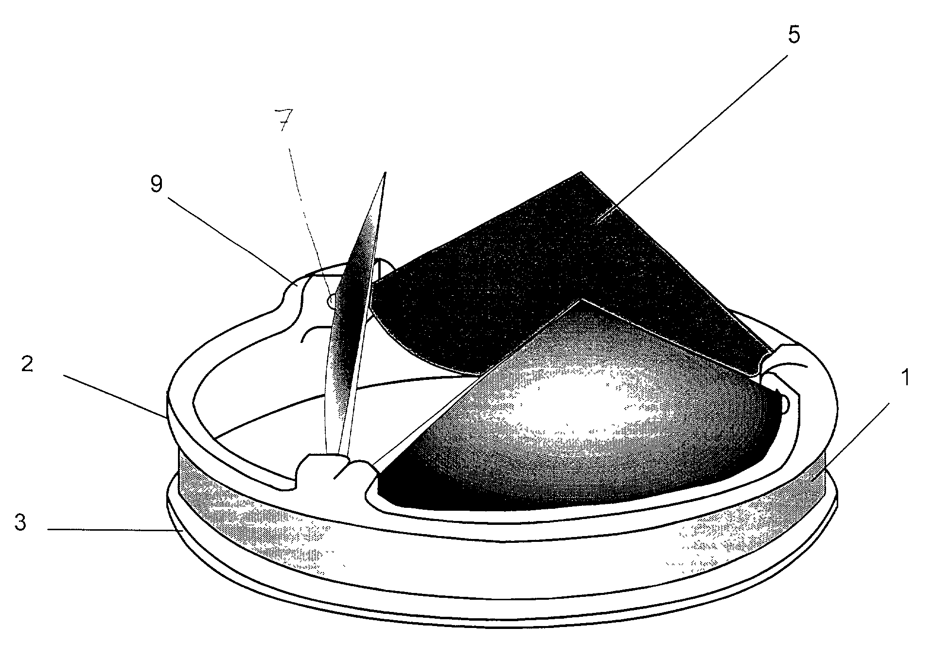
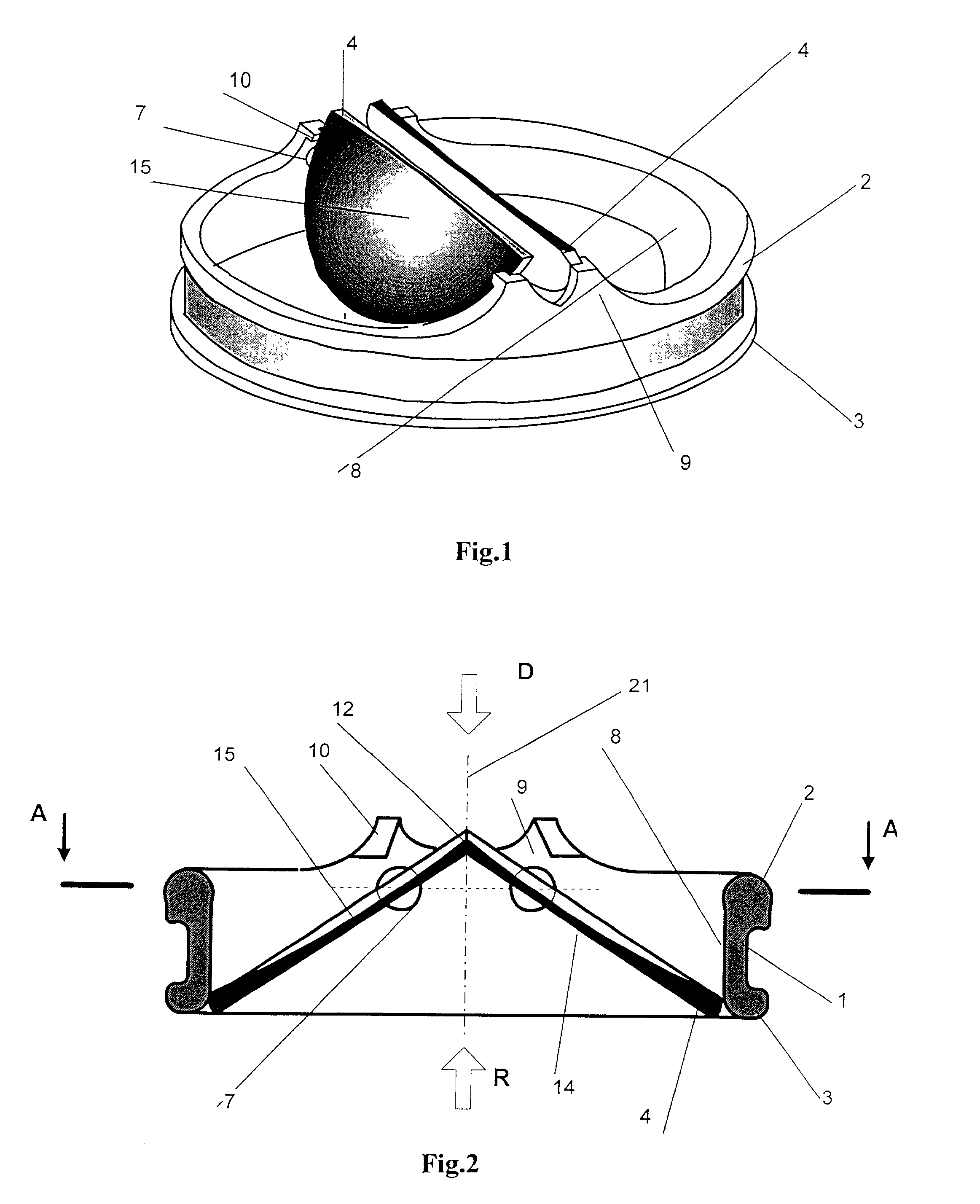
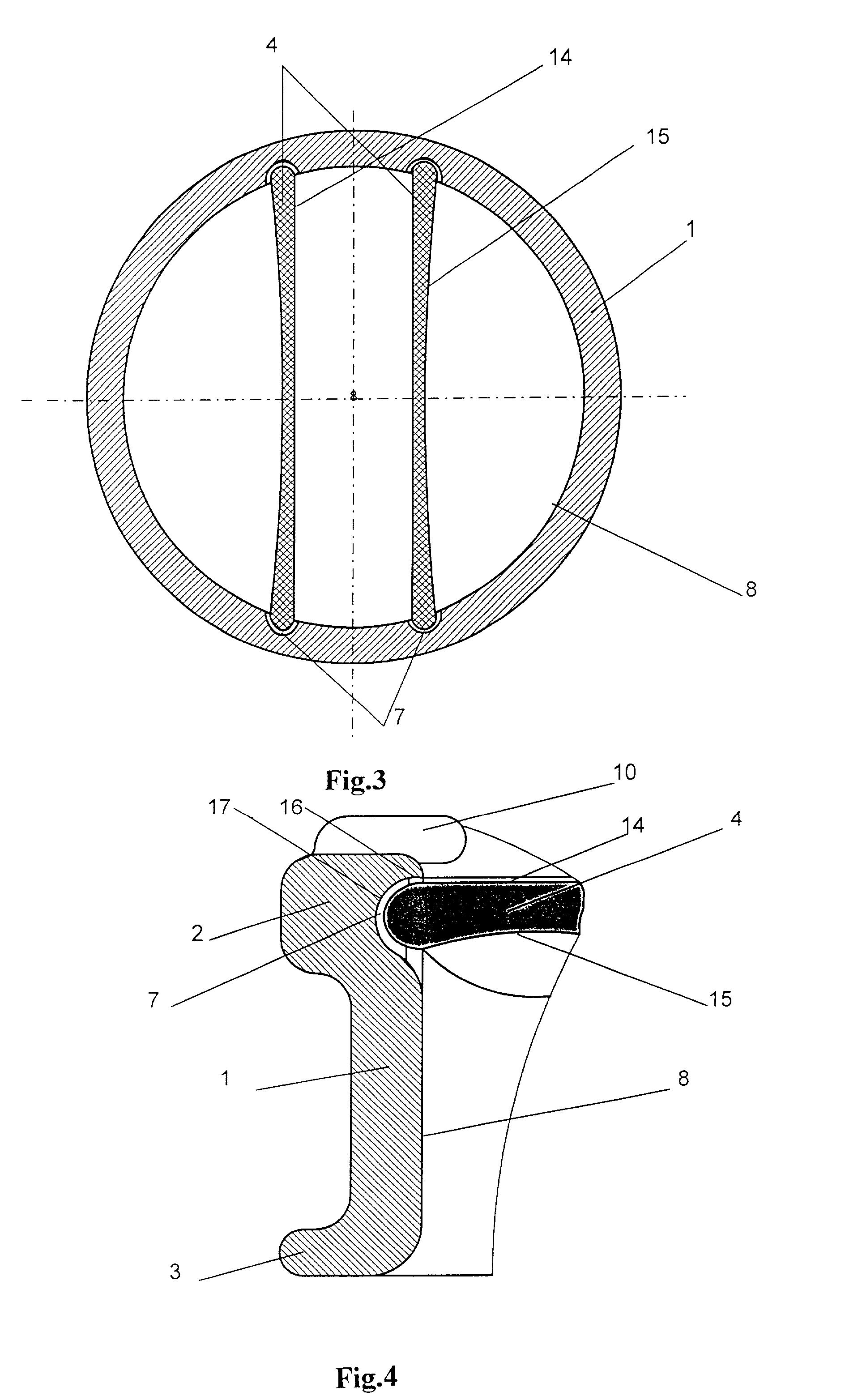
[0026] A heart valve prosthesis comprises an annular body 1 with a pair of flanges 2, 3, and a closing element in the form of two flaps 4 or three flaps 5, which are mounted through bearings 6 in recesses 7 of the body 1 with freedom to be rotated. In the embodiment with two flaps the interior surface 8 of the body 1 about the entire periphery is cylindrical with no protrusions, that is the flow section of the annular body 1 has a form of a circle and is not varied at different levels (FIG. 1). Body 1 has a constant height on a greater portion of a ring circle, and ledges 9, the number of ledges being equal to that of the flaps. Ledges 9 are provided with rotation limiters of the flaps 4 or 5. In the preferable embodiment, the ledges 9 are W-shaped and their interior surface from the side of the direct flow of blood is inclined towards the central axis of the body 1.

[0027] The flaps 4 and 5 have ascending and descending surfaces oriented towards a direct and a reverse flow of blood,...


PUM


Abstract

The present invention relates to medical techniques and can be used in heart surgery for the replacement of the damaged natural aortal and mitral human heart valves and also tricuspid and lung artery valves. A heart valve prosthesis comprises an annular body with a pair of flanges, and a closing element in the form of two or three flaps mounted by means of bearings into the body's recesses with freedom to be rotated. The body has a constant height on a greater portion of a ring circle, and ledges the number of which is equal to that of the flaps. The ledges are provided with flap rotation limiters. In the preferable embodiment, the ledges are W-shaped while their interior surface from the side of the direct flow of blood is inclined to the central axis of the body. The flaps have ascending and descending surfaces oriented to the direct and reverse flows of blood, respectively, a side edge and an edge for joining the other flap. The descending surface of a flap is flat and the ascending surface thereof is spherically concave. The flaps have the minimal thickness on an axis of symmetry at the joining edge. In the event when a closing element comprises three flaps, each of them has two joining edges obliquely converging toward the body's central axis. Also, the axes of rotation of the flaps will be arranged relative to each other at an angle of 60° thereby to form the sides of an equilateral triangle. For the valve with two flaps the flange facing the direct flow of blood is thickened. Recesses for bearings enter into the thickened flange, said recesses having a lateral cylindrical surface and a concave bottom. The recesses for bearings can be configured as a triad of blind holes being in communication, which is comprised of one central and two side holes. And the radius and depth of the central hole are greater than the radii and depths of the side holes.

Description

[0001] The present invention relates to medical techniques and can be used in heart surgery for the replacement of damaged natural aortal and mitral human heart valves. The invention can also be put to use in replacing affected tricuspid and lung artery valves.PRIOR ART[0002] Known in the art is a heart valve prosthesis (U.S. Pat. No. 4,276,658, 1981) comprising an annular body with a pair of ledges on a surface facing a forward flow of blood, and two flaps which are provided with bearings on the side edges of each and every flap. The bearings hingeably enter into recesses on the interior surface of the body's ledges, which permits closing and opening the flaps by rotation. The recesses on the body of the prosthesis have a spherical bottom defined by two V-like rotation limiters, which are adapted to be operatively engaged, by lateral surfaces thereof, with the flap bearings. The interior surface of the body has two diametrically opposed flat portions.[0003] With such a construction...

Claims


Application Information

Patent Timeline
Patent Type & Authority Applications(United States)
IPC IPC(8): A61F2/24
CPCA61F2/2403
Inventor SAMKOV, ALEXANDR VASILIEVICHIOFIS, NAUM ABRAMOVICHAGAFONOV, ANDREJ VASILIEVICH
Owner SAMKOV ALEXANDR VASILIEVICH
Why Eureka
Try Eureka