Heat supply system

a heat supply system and hot water technology, applied in water feed control, fire-box steam boilers, heating types, etc., can solve the problems of high initial cost, large heat emission loss, and defects in the hot water supply system described

Inactive Publication Date: 2002-03-07
MARUYAMA NOBORU
View PDF0 Cites 9 Cited by
  • Summary
  • Abstract
  • Description
  • Claims
  • Application Information

AI Technical Summary

Benefits of technology

0011] With the present invention, a heat medium heated by the heat exchanger is sent through the feed main pipe, feed branch pipe and load pipe to a load member. The heat medium thermally consumed by the load member returns through the first return branch pipe, second return branch pipe, and return main pipe to the heat exchanger, and is heated again. With the piping system as described a...

Problems solved by technology

The hot water supply system as described, however, has the defects as described below.
For the reasons described above, it is necessary to provide a number of pipes having differe...

Method used


Image

  • Heat supply system
  • Heat supply system
  • Heat supply system

Examples


Embodiment Construction

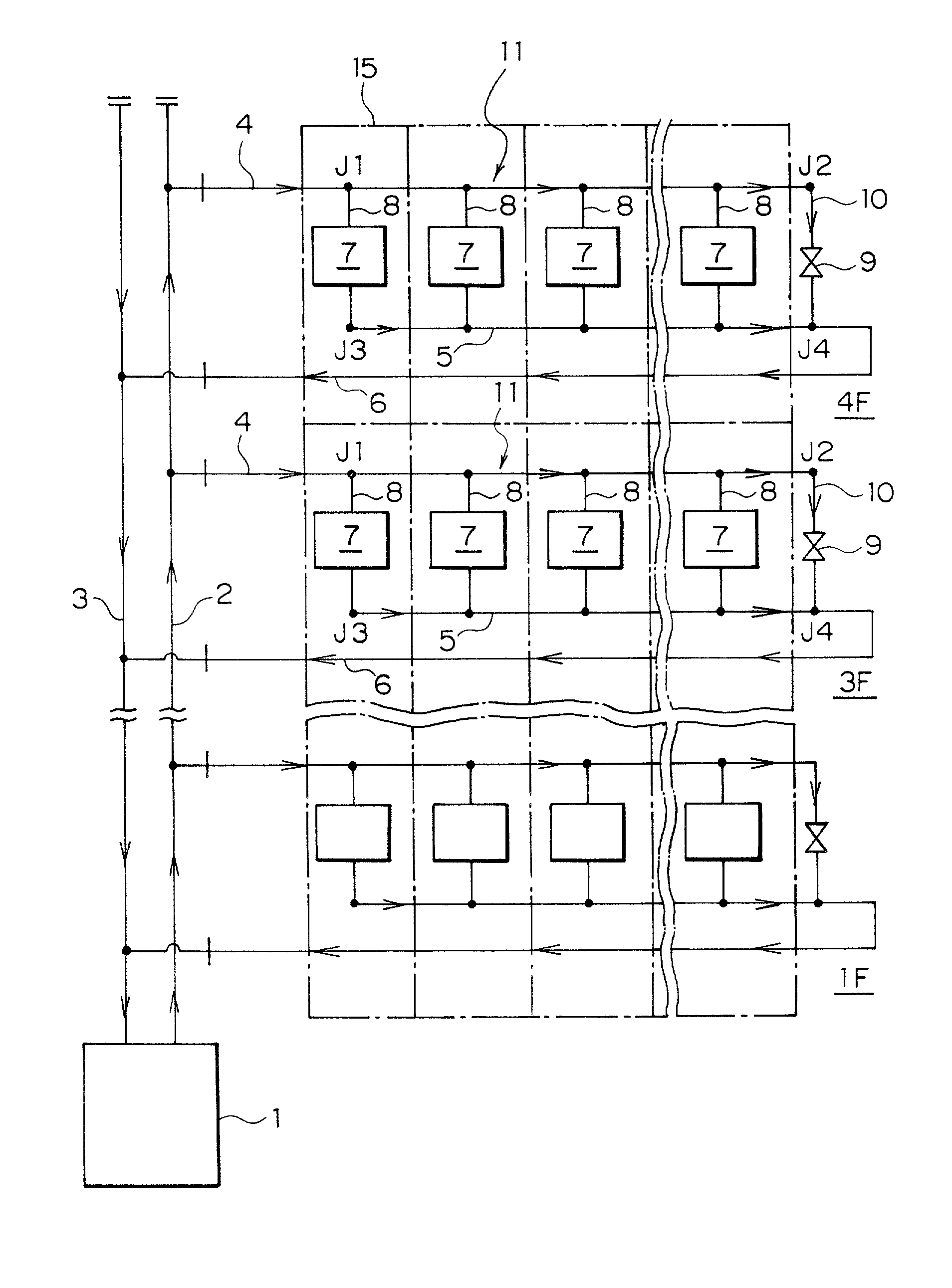
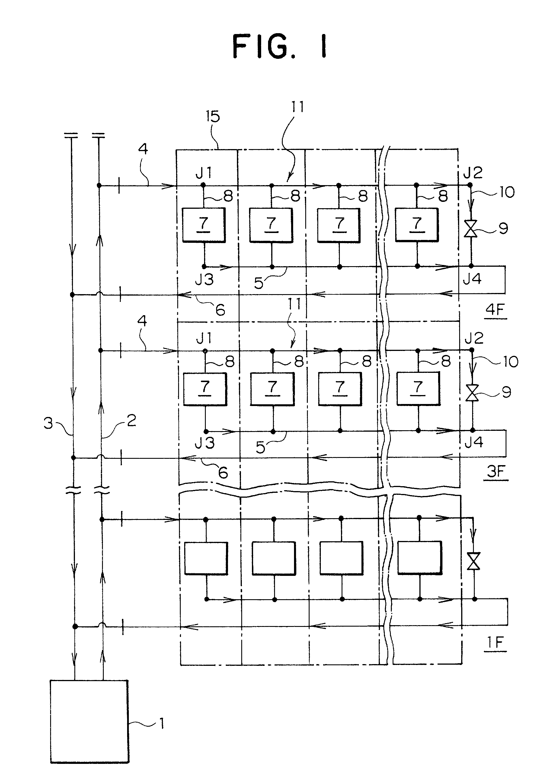
[0023] Embodiments of the present invention are described in detail below with reference to the related drawings. FIG. 1 is a piping system diagram showing an embodiment of the present invention.

[0024] FIG. 1 shows with chain lines a building 15 (a four-storied one) consisting of multiple floors in which the heat supply system according to the present invention is applied. A feed main pipe 2 and a return main pipe 3 are provided outside the building 15 and are connected to a heat exchanger 1.

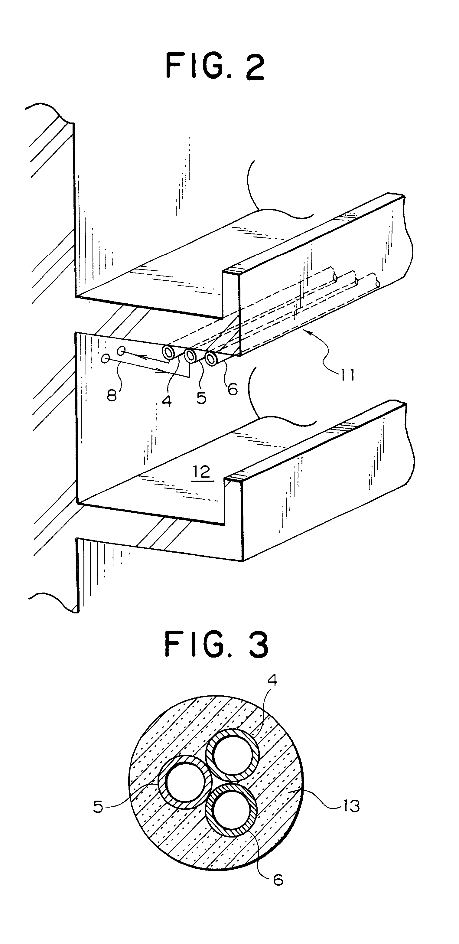
[0025] A feed branch pipe 4, a first return branch pipe 5, and a second branch pipe 6 are provided in the lateral direction outside each floor of the building 15, and a feed branch pipe 4 is connected to a feed main pipe 2. A plurality of load pipes 8 corresponding to compartments adjoining each other in the lateral direction are connected in parallel to each other, and load members 7 are provided in each load pipe 8. The load members 7 include boilers and heating equipment, and are provided in ...


PUM


Abstract

A heat supply system is provided which enables use of small pipes with the same diameter for both feed branch pipes and return branch pipes, thus reducing the initial cost and also suppressing heat emission loss. The heat supply system comprises a heat exchanger 1, a feed main pipe 2, a return main pipe 3, a feed branch pipe 4 connected to the feed main pipe 2, a first return branch pipe 5 for directing the flow of a heat medium to an edge section in the downstream side of the feed branch pipe 4, a plurality of load pipes connected in parallel to a section between the feed branch pipe 4 and the first return branch pipe 5 each having a load member 7 provided thereon, and a second return branch pipe 6 connected to a section between an edge section in the downstream side of the first return branch pipe 5 and the return main pipe 3, said heat supply system having a plurality of branch pipe paths 11 including therein the feed branch pipe 4, first return branch pipe 5, load pipe 8, and second branch pipe 6.

Description

[0001] 1. Field of the Invention[0002] The present invention relates to heat supply systems. More particularly, this invention relates to a heat supply system for use in a building having a number of separate and distinct compartments, such as an apartment house, a general office building, and a plant.[0003] 2. Prior Art[0004] In recent years, unified heat supply systems have been employed for supplying heat in buildings such as described above by circulating a suitable fluid heat carrying medium, such as water, heated by a heat exchanger, to load members such as boilers, heating equipment, and driers. FIG. 10 in the drawings is a piping diagram showing a conventional type of such a supply system in a building 50, which is a 4-storied collective housing one. As shown in FIG. 10, a feed main pipe 52 and a return main pipe 53, each provided in the lateral direction, are connected to a heat exchanger 51 provided on the ground floor. A plurality of pipe shafts 60 extend through each of ...

Claims


Application Information

Patent Timeline
IPC IPC(8): F24D3/02F24H1/26
CPCF24D3/02F24H1/26
Inventor MARUYAMA, NOBORU
Owner MARUYAMA NOBORU
Why Eureka
Try Eureka