Supercharge Your Innovation With Domain-Expert AI Agents!

Elastomeric tensioning system for head and ear mounted eyewear

a tensioning system and elastomeric technology, applied in the field of athletic sunglasses, can solve the problems of inability to conveniently remove and store sunglasses from the viewing position, ear and nose soreness, and the shape and construction of the human head do not lend themselves well to attaching ordinary sunglasses to the protruding protruding parts

Inactive Publication Date: 2002-03-14
HILL JOE D
View PDF0 Cites 15 Cited by
  • Summary
  • Abstract
  • Description
  • Claims
  • Application Information

AI Technical Summary

Problems solved by technology

Unfortunately, the shape and construction of the human head does not lend itself well to attaching ordinary sunglasses to its protrusions.
The result of these two opposite forces is sore ears and a sore nose.
The other problem of ordinary sunglasses is the inability to conveniently remove and stow the sunglasses from the viewing position when conditions require.
However, this design is fragile because of the single tiny flip up mechanism used to attach the eyepiece to the headband.
This one fragile attachment point would allow even the smallest of impacts experienced during a sports activity to drive the eye pieces into the wearers eyes and face, posing an unacceptable risk of damage.
This approach is not only cumbersome and time consuming for the hands to operate, but more importantly, it drastically limits the size and shape of the eyepieces that can be used because of the need to fit inside the headband when not in use.
Since these eyepieces are too small and too flat to adequately follow the contours of the head and face, unfiltered sunlight as well as foreign objects are allowed to reach the eyes from the sides and bottoms of the eyepieces.
Although the eyepiece gave better eye protection, it was still cumbersome and unwieldy to operate by requiring two hands to change the position of the eyepiece.
However, no tensioning system was provided to keep the eyepiece firmly in place in the two desired positions.
And finally, the eyepiece had to rotate into a cap bill, thus limiting its travel, making the design unsuitable for a vigorous sport like basketball.
The second drawback is the obvious sliding friction required to expand the journalling opening for the journalling pin to rotate.
However, there is no tensioning system to raise and lower the eyeshield, plus a fragile single attachment and rotation point for the eyeglasses makes this design unsuitable for aggressive sports.
The design however, has no tensioning device to raise and lower the eyeshield, but instead uses the wearer's chin to perform this function.
This design is not only cumbersome, but also limited in its applications in sports.
Tension is provided to assist the upward rotation of the eyeshield, but provides no assistance in the lowering of the eyeshield, thus the design must use snap catches on each side to keep the eyeshield from springing upward during line of sight use.
The drawback of using a spring-operated system is the bulky nature of their design.
Springs do provide tension, but at the expense of precious available space around the forehead.
This design also required the considerable bulk and space inherent in the use longitudinal coiled springs.
However, this design also has deficiencies that have prevented the design concept from reaching its maximum efficiency in the operation of the tensioning system, and the efficiency of the adjustability features.
Also, the O-ring design itself is deficient in maximizing the force available to lift and lower the lens.
This simple O-ring design does not incorporate the advantages of multiple segments located inside the middle area of the O-ring.
By having a single continuous body, space is wasted in the interior area of the O-ring that could be used to provide more force for the same occupied area by adding additional reinforcing material.
This bending of the O-ring around a stationary non-rotating post induces efficiency losses that can be measured at the end of the arm where it attaches to the lens.
This design is both complex and costly for a simple task of adjusting the lens to the face of the wearer.
While this patent cures many of the problems already listed and discussed, it suffers from some limitations.

Method used


Image

  • Elastomeric tensioning system for head and ear mounted eyewear
  • Elastomeric tensioning system for head and ear mounted eyewear
  • Elastomeric tensioning system for head and ear mounted eyewear

Examples


Embodiment Construction

[0089] The following embodiments of this invention are not the only ways of achieving the described features by others skilled in the art.

[0090] The following description of some of the preferred embodiments of this invention will make reference to the accompanying figures. Where an individual mechanical part is shown in more than one figure, it is assigned a common reference number for ease of identification and understanding.

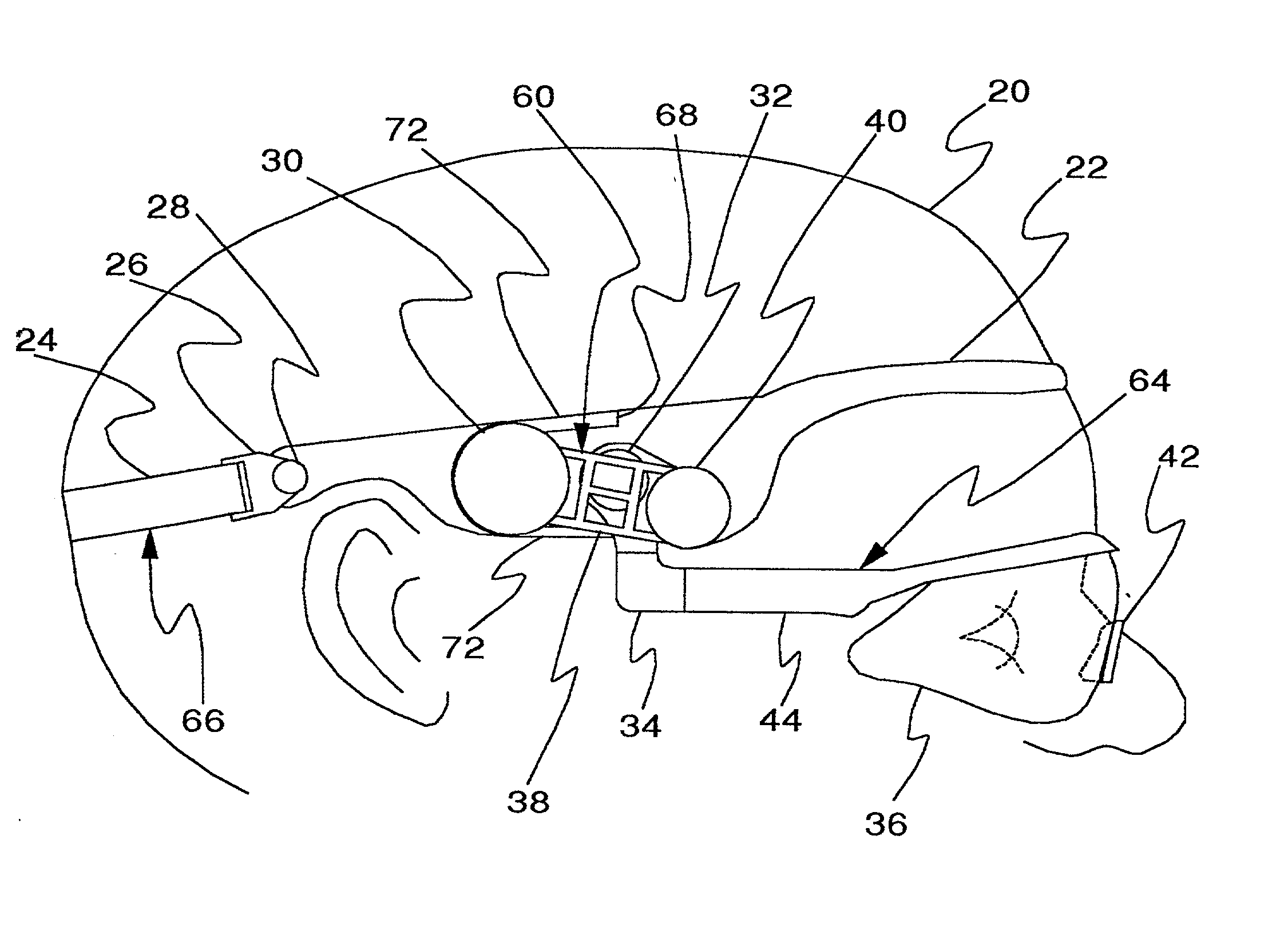
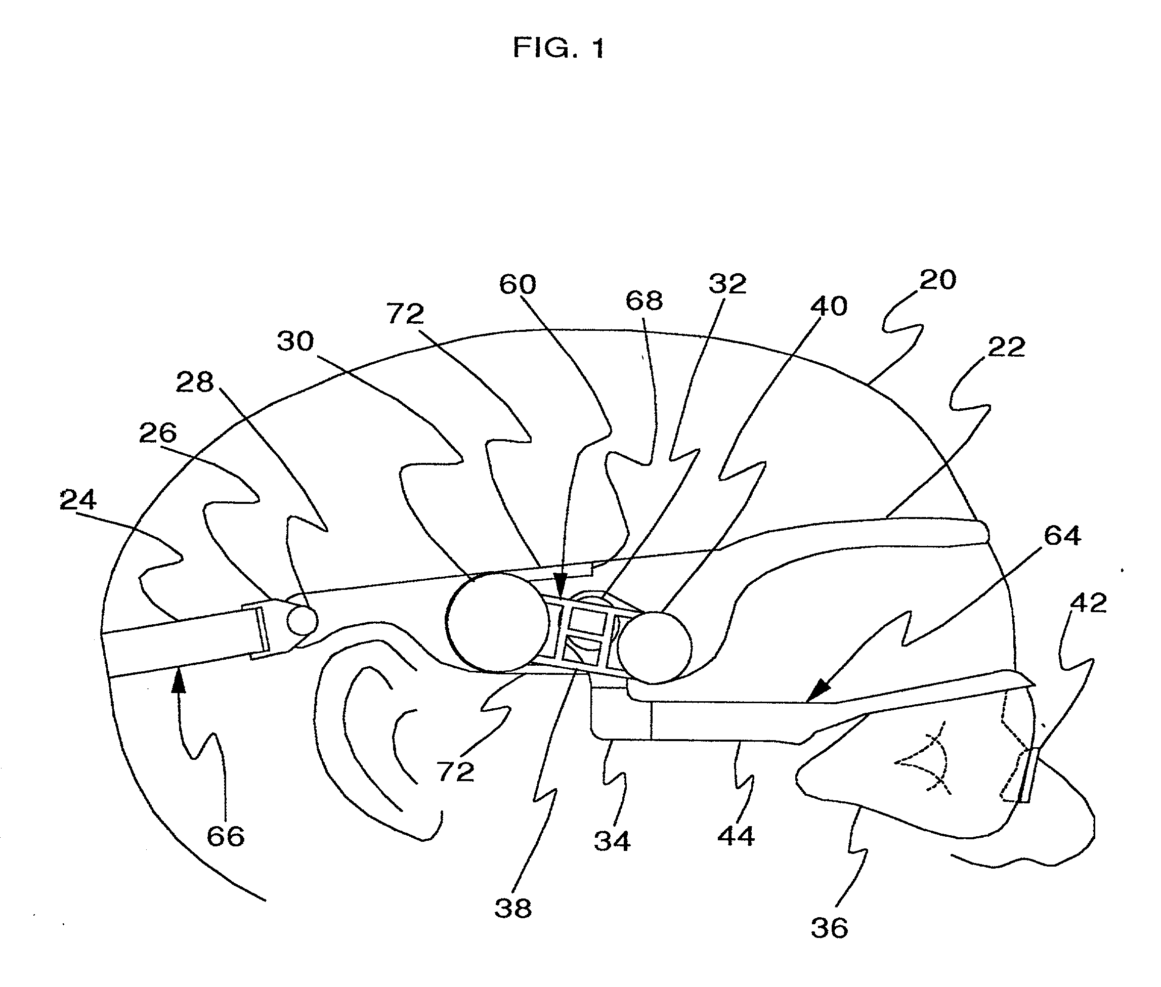
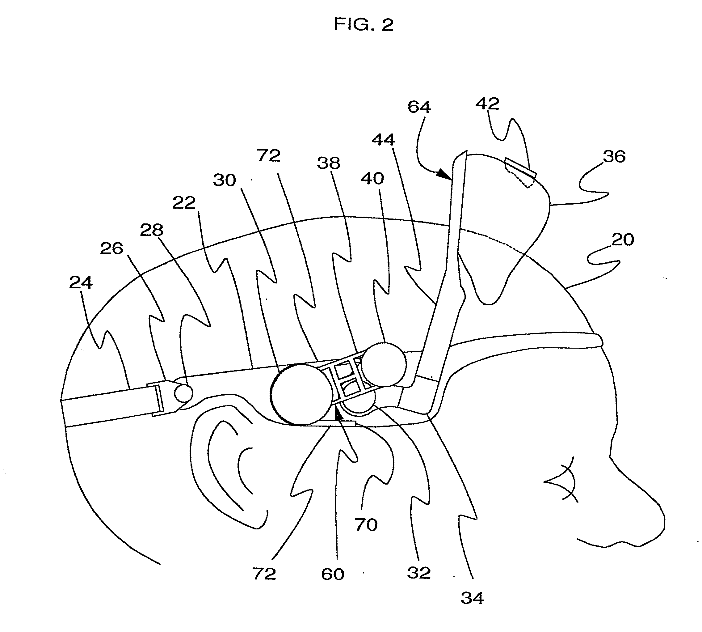
[0091] FIG. 1 shows the basic invention secured on the head of the wearer (20) in the viewing position. FIG. 2 shows the basic invention secured on the head of the wearer (20) in the out of viewing position. The invention consists of four basic parts: head mount support (22), FIG. 5, elastomerically operated tensioning system (60), FIG. 1 and FIG. 6, lens assembly (64), FIG. 5, and pivoting adjustable elastic strap assembly (66) FIG. 5.

[0092] Referring to FIG. 5, head mount support (22) is a one piece plastic injection molded part 0.060 inches thick, 14 inches...


PUM


Abstract

A curved optical eye shield removably attached to a single set of arms that connect to an elastomerically operated tensioning system that is an integral part of ahead mount system. The eye shield rotates from a normal viewing position to an out of viewing position above the forehead. The rotation of the eye shield is initiated manually, but, the elastomerically operated tensioning system contemplates the rotation unassisted after the eye shield passes midway in its travel. The elastomerically operated tensioning system uses an H shaped tensor to apply clockwise tension to keep the eye shield held firmly in the viewing position, and when the eye shield is manually lifted toward the out of viewing position above the forehead, tension is applied to the reverse or counter clockwise direction to keep the eye shield held firmly in the out of view position.

Description

[0001] Priority for this application is claimed from United States Provisional application serial number 60 / 197,973, filed on Apr. 18, 2000, and entitled "Elastomeric Tensioning System for Head and Ear Mounted Eyewear".[0002] 1. FIELD OF INVENTION[0003] This invention relates to athletic sunglasses with a head mounted elastomerically powered tensioning system used to rotate a lens from the viewing position in front of the eyes, to a nonviewing position above the forehead.[0004] 2. Description of Prior Art[0005] Outdoor athletes today are more cognizant than ever of the need to wear sunglasses as a protective barrier from the elements. Sunglasses shield the eyes from accidental invasion of foreign objects, and provide protection from the sun's ultraviolet A, 315 to 400 nanometers, and ultraviolet B, 280 to 315 nanometers, radiation levels.[0006] Although sunglasses have been around for a long time, the basic design remains the same. Two earpieces that attach to a lens frame, that att...

Claims


Application Information

Patent Timeline
Patent Type & Authority Applications(United States)
IPC IPC(8): A61F9/02
CPCA61F9/025A61F9/026
Inventor HILL, JOE D.
Owner HILL JOE D
Features
  • R&D
  • Intellectual Property
  • Life Sciences
  • Materials
  • Tech Scout
  • Unparalleled Data Quality
  • Higher Quality Content
  • 60% Fewer Hallucinations
Learn More