Method and apparatus for lining a conduit

Inactive Publication Date: 2002-03-21
HEAGY RICHARD T +3
View PDF34 Cites 45 Cited by
  • Summary
  • Abstract
  • Description
  • Claims
  • Application Information

AI Technical Summary

Problems solved by technology

Access to such pipes is often difficult and the excavation required to dismantle and/or remove the pipes can be expensive, disruptive, and time-consuming.
One disadvantage of such systems is the increased costs associated with having to presoak the fabric with resin before it is inserted within the host conduit.
Special equipment is required to "wet" the fabric, and it is difficult to handle the "wet" fabric while attempting to install it into the host conduit.
Another disadvantage of these systems is the relatively high cost of the fabric or fiber and the relatively high labor costs associated with fabricating the tubes.
Additionally, the use of "presoaking" methods typically results in "fiber-weakening," which causes a reduction in strength of the newly formed liner

Method used


Image

  • Method and apparatus for lining a conduit
  • Method and apparatus for lining a conduit
  • Method and apparatus for lining a conduit

Examples


Embodiment Construction

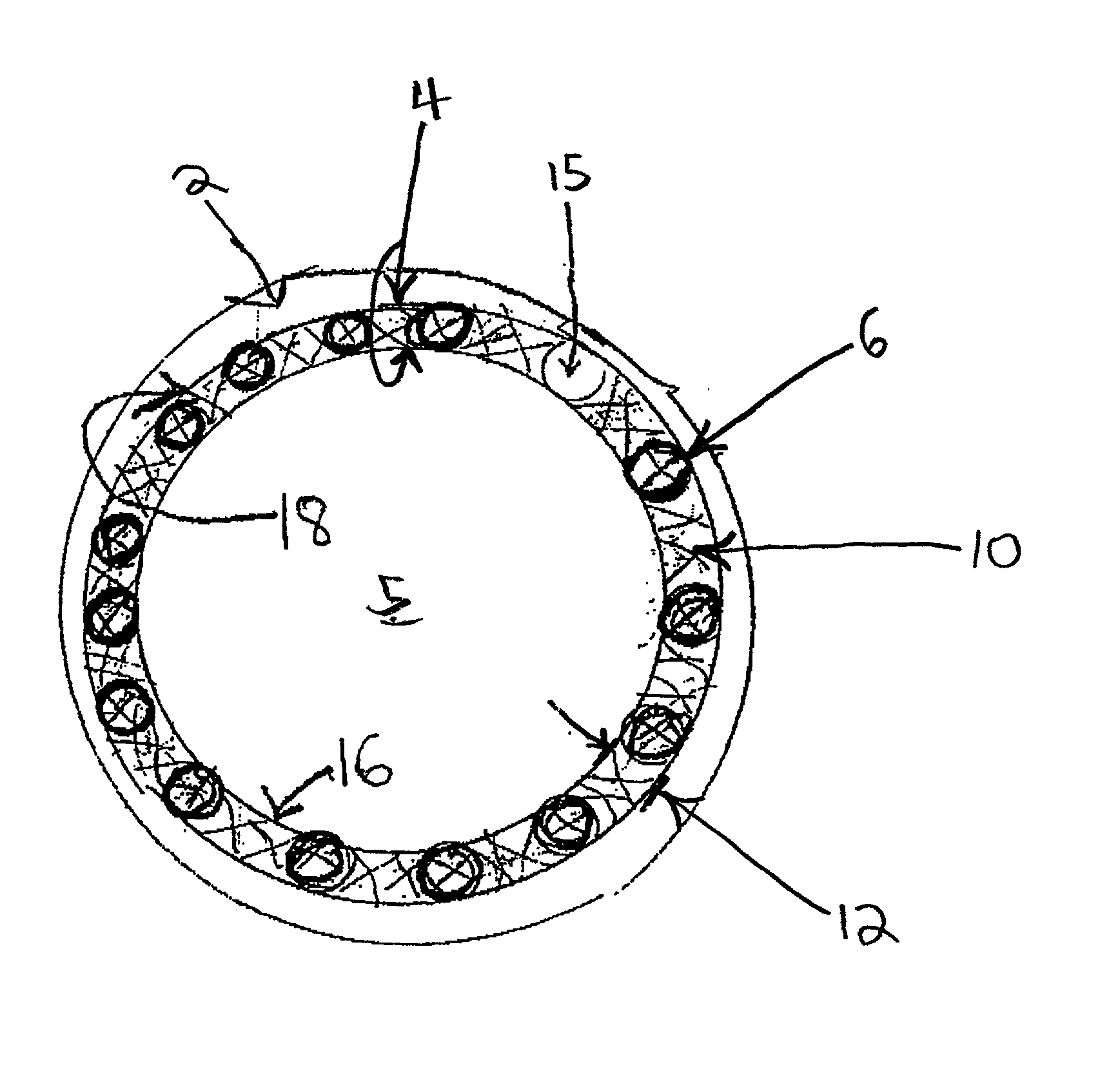
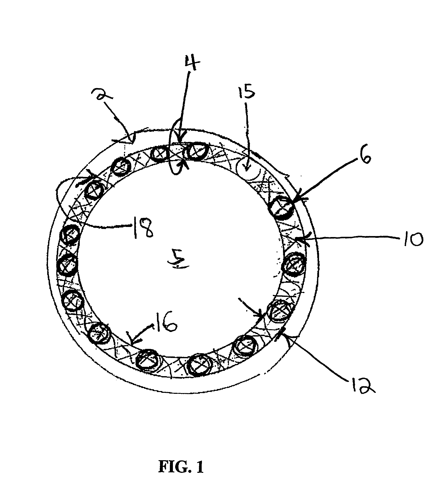
[0082] FIG. 1 depicts an embodiment of a lined conduit constructed in accordance with the present disclosure. The host pipe or host conduit 2 contains a liner material 4 fixed (directly or indirectly) to the inner surface of the host conduit 2. Host conduit 2 can be any pipe or vessel (e.g., an underground sewer pipe) that is adapted to transport or contain a fluid (e.g., liquid, gas, mixture of liquid and gas, etc.). The liner material 4 forms a liner or shell to separate conduit 2 from materials (such as solids, corrosive materials, etc.) that are contained in the fluid transported through the host conduit. The liner material may be used to form a new pipe within the host conduit 2. The liner material 4 is thus preferably impermeable to the fluid and materials contained in the lumen or bore 5 of conduit 2. The liner material 4 may also be useful to correct defects in the host conduit due to corrosion or crumbling.

[0083] The liner material 4 is preferably substantially flexible and...


PUM

PropertyMeasurementUnit
Lengthaaaaaaaaaa
Angleaaaaaaaaaa
Viscosityaaaaaaaaaa

Abstract

Method and apparatus for installing a liner material into a host conduit such as, e.g., a sewer pipe, hydrocarbon pipeline, gas line, water line, industrial chemical pipe, or a saltwater line. The liner material may include a compression liner and/or a preliner that is attached to the inner wall of the host conduit to repair or reinforce the host conduit or separate the host conduit from materials transported within the new liner formed from the liner material. Curable resin, slurry, or cement can be placed between the liner material and the host conduit to affix the liner material into place. Before and during curing, a fluid such as air or water can be used to inflate the compression liner outwardly toward the host conduit. Spacers positioned between at least a portion of the liner material and the host conduit may be used to (i) calibrate the thickness of the liner material and curable material that is cured to form the new liner, and (ii) form communication channels adapted to house devices such as wire, cable, fiber optic cable, telephone lines, power lines, etc. The spacers and channels can be selectively inflatable to various sizes to allow calibration of the liner thickness and to form communication channels having a selected width or height. Additionally, the liner material may be formed into a one-piece, tubular lining member having an inflatable enclosure defined between an inner and an outer layer of the lining member. The enclosure can be selectively inflated to (i) calibrate the resulting thickness of the cured liner material, and (ii) form communication channels running along the length of the host conduit.

Description

[0001] This application claims priority based upon U.S. Provisional Application No. 60 / 210,368 filed on Jun. 9, 2000, which is incorporated by reference as if fully set forth herein.[0002] 1. Field of the Invention[0003] The present invention generally relates to lining the interior of a host conduit (e.g., pipe, vessel, etc.) with a liner material to repair or reinforce the conduit or separate the conduit from materials that are contained or transported through the newly formed liner within the conduit. More particularly, an embodiment of the invention relates to fixing a liner material into a conduit with curable material wherein spacers are inserted between at least a portion of the liner material and the conduit in order to calibrate the thickness of the liner material and to create communication channels lengthwise along the conduit for housing devices such as wires and fiber optic cables for carrying communication signals. The host conduit can be any pipe for containing fluids...

Claims


Application Information

Patent Timeline
IPC IPC(8): B29C35/02B29C35/08B29C63/34F16L55/165
CPCB29C35/02B29C63/34B29C2035/0827B29K2105/06B29L2024/00B29L2024/006F16L55/165F16L55/1654
Inventor HEAGY, RICHARD T.HEAGY, CYNTHIA D.MENGER, TOM R.SIMONIS, JOHN
Owner HEAGY RICHARD T
Why Eureka
Try Eureka