Self-contained flight data recorder with wireless data retrieval

Inactive Publication Date: 2002-03-21
MICROLOGIC SYST
View PDF0 Cites 155 Cited by
  • Summary
  • Abstract
  • Description
  • Claims
  • Application Information

AI Technical Summary

Problems solved by technology

These are highly expensive systems that consist of several heavy and bulky pieces of equipment and a multitude of sensors and cables deployed throughout the aircraft, makin

Method used


Image

  • Self-contained flight data recorder with wireless data retrieval
  • Self-contained flight data recorder with wireless data retrieval
  • Self-contained flight data recorder with wireless data retrieval

Examples


Embodiment Construction

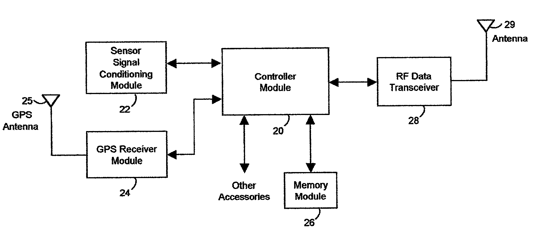
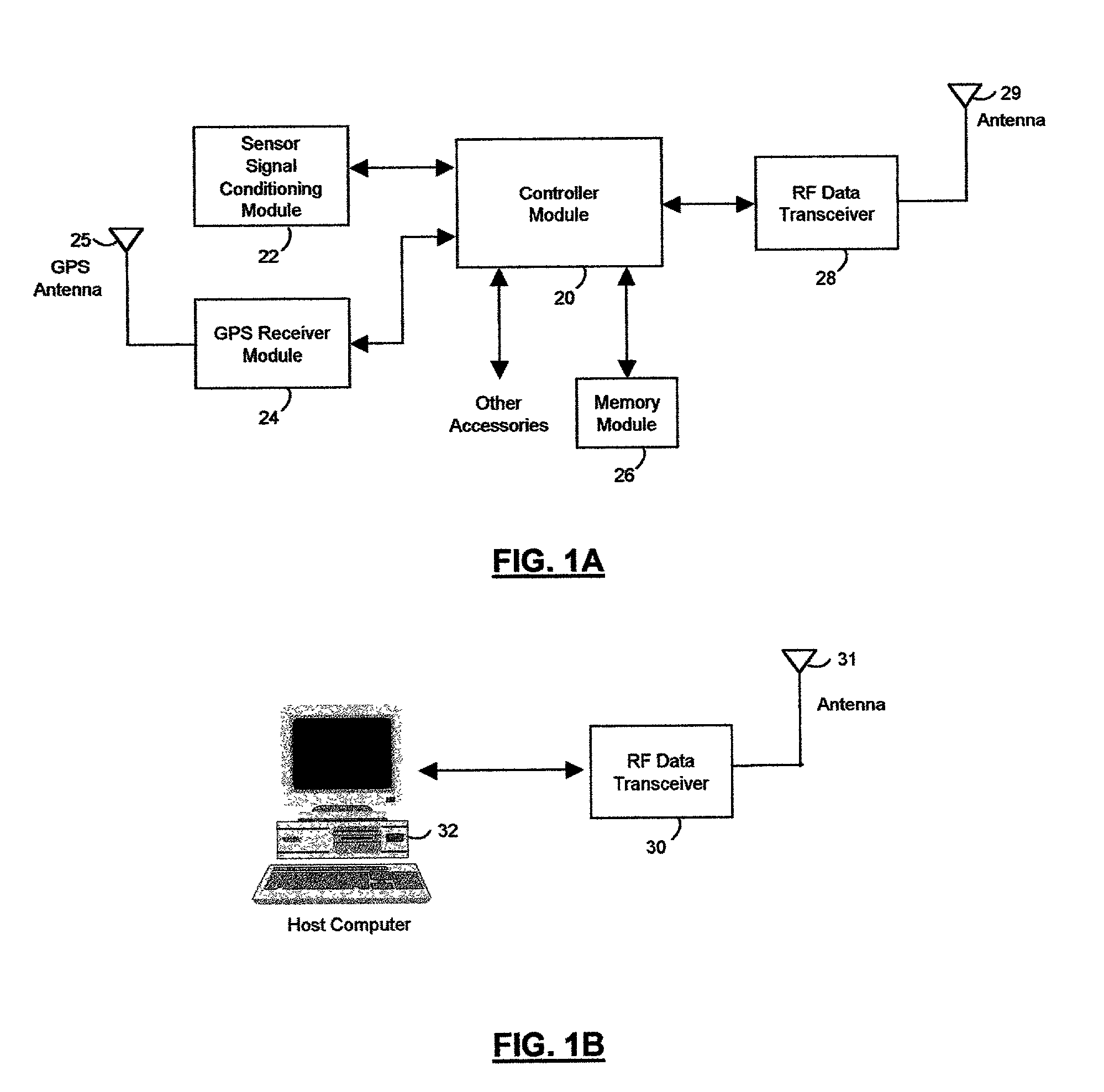
[0048] The main components of the flight data recorder are shown in the block diagrams of FIG. 1A and IB. The onboard flight data recorder unit is shown in FIG. 1A. A controller module 20 performs the functions of processing the analog signals from a sensor and signal conditioning module 22 which are converted to digital form and then stored by the controller module 20 in its non-volatile memory. A GPS (Global Positioning System) receiver module 24 generates location and information and controller module 20 stores it in its non-volatile memory. In addition, the captured data are also stored in an external memory module, which serves as a back-up. The recorded data are retrieved from memory through the use of a radio frequency data transceiver module 28 together with an antenna 29, providing two-way communications capability to a retrieving device.

[0049] GPS receiver module 24 receives signals from several orbiting navigation satellites called Navstar, using an antenna 25. It uses th...


PUM


Abstract

A flight data recorder designed for small aircraft captures various onboard flight data in real-time and stores it in non-volatile memory. Recorded data includes aircraft's instantaneous position, altitude, attitude, engine RPM, G forces, flap position, cockpit voice and others. These data are obtained from various sensors which are integrated into the recorder. At the end of a flight the recorded data is downloaded into a computer using a wireless communications data transceiver also integrated into the recorder. It is an inexpensive system that does not require interfacing to any of the aircraft's instruments. It does not require removal or attaching any equipment to be able to download data. In addition to accident investigation, applications include training, preventive maintenance and asset monitoring.

Description

[0001] This application claims the benefit of Provisional Patent Application No. 60 / 189,581, filed Mar. 15, 2000.[0002] 1. Field of the Invention[0003] This invention relates to aviation, specifically to flight data recording systems as applied to light aircraft.[0004] 2. Description of Prior Art[0005] Most flight data recorders are designed for use in accident investigation in large aircraft such as wide-body airline jets. These are highly expensive systems that consist of several heavy and bulky pieces of equipment and a multitude of sensors and cables deployed throughout the aircraft, making it impractical for use in light aircraft. Recorded data is retrieved by attaching a portable device to the recorder or by physically removing the recorder and bringing it to a retrieval facility. They are designed to withstand very high temperatures for prolonged periods, great impact forces and deep submersion in water. These are the usual environmental conditions present during a violent cr...

Claims


Application Information

Patent Timeline
IPC IPC(8): B64D45/00B64F5/00G07C5/00
CPCG07C5/008
Inventor DE LEON, HILARY LAING
Owner MICROLOGIC SYST
Why Eureka
Try Eureka